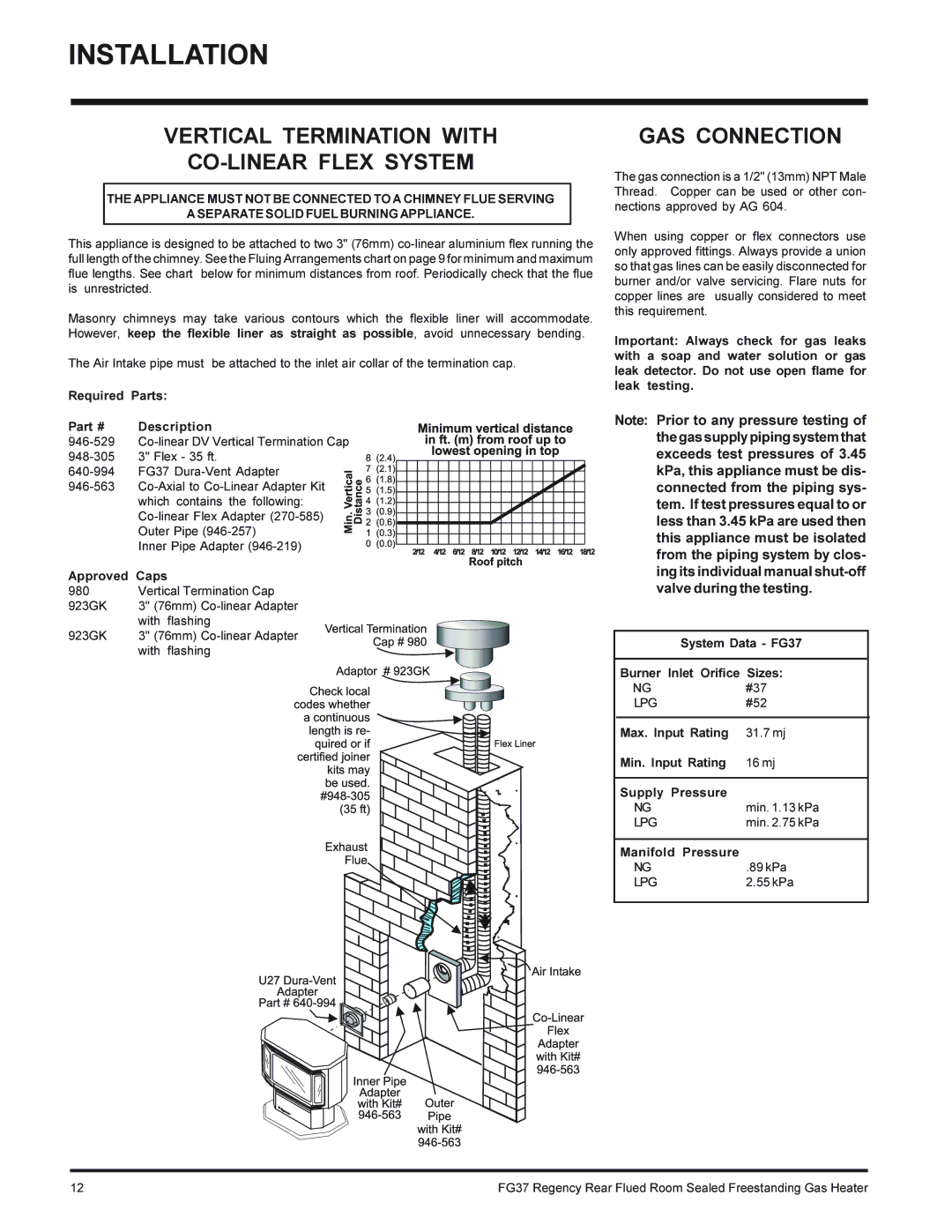
FG37-NG, FG37-LPG specifications
The Regency FG37-LPG and FG37-NG are premium gas fireplaces that blend elegance with cutting-edge technology, making them ideal for modern homes. Designed by Regency, a leader in the fireplace industry, these models offer both aesthetic appeal and highly efficient heating capabilities.The FG37-LPG is powered by liquid propane, while the FG37-NG utilizes natural gas, providing versatile options to meet different customer needs. Both models feature a sleek, contemporary design that complements various interior styles, making them a focal point in any living space. The large viewing area allows for an expansive display of flames, contributing to a warm, inviting atmosphere.
One of the standout features of the Regency FG37 series is its advanced heating technology. The fireplaces employ a high-efficiency burner system that maximizes heat output while minimizing gas consumption. This efficiency not only leads to lower energy bills but also reduces environmental impact, aligning with sustainability goals.
Additionally, the Regency FG37 models feature advanced flame control technology. Users can easily adjust the flame intensity, allowing for a custom heating experience that suits personal preferences and room sizes. This versatility makes them suitable for a variety of applications, from cozy family rooms to expansive open-concept spaces.
For added convenience, the fireplaces are equipped with a modern electronic ignition system, ensuring reliable and hassle-free startup. Customers appreciate the included remote control, which provides effortless operation from the comfort of their seats. As an optional upgrade, the Regency Smart Home Control system allows for integration with smart home devices, enabling users to manage their fireplace from their smartphones or tablets.
Safety is paramount in the design of the FG37-LPG and FG37-NG. Both models come with a built-in safety shutoff valve, ensuring that the gas supply is automatically cut off in the event of an emergency. The units also feature a glass door that remains cool to the touch, providing peace of mind for households with pets and children.
Overall, the Regency FG37-LPG and FG37-NG epitomize the perfect merger of style, efficiency, and safety. With their striking design, advanced technologies, and user-friendly features, these gas fireplaces are an excellent choice for anyone seeking to enhance their home with the luxury and warmth of a modern fireplace.

