M65881AFP
SERIAL CONTROL
1. Gain Control Mode |
| No setting bits means " Don't care". | ||||
|
|
|
| |||
bit | Flag name | Functional Explanation | H | L | INIT | |
1 | MODE1 | Mode setting1 |
| "L" fixed | – | |
2 | MODE2 | Mode setting2 |
| "L" fixed | – | |
3 | TEST1 | Test Mode 1 |
| "L" fixed | L | |
4 | TEST2 | Test Mode 2 |
| "L" fixed | L | |
5 | NSLMT1 | Output Limit 1 | Refer to Table | L | ||
6 | NSLMT2 | Output Limit 2 | L | |||
|
| |||||
7 | GCONT1 | Channel selection for Gain Control Block 1 | L/R Independence | L/R Common | L | |
8 | GCONT2 | Channel selection for Gain Control Block 2 | Lch | Rch | L | |
9 | NSPMUTEL | Lch Duty 50% Mute for PWM Output | active | L | ||
10 | NSPMUTER | Rch Duty 50% Mute for PWM Output | active | L | ||
11 |
|
|
|
| – | |
12 | GAIN0 | Gain Data Index (MSB) |
|
| H | |
13 | GAIN1 | Gain Data Index |
|
| L | |
14 | GAIN2 | Gain Data Index |
|
| L | |
15 | GAIN3 | Gain Data Index |
|
| L | |
16 | GAIN4 | Gain Data Index (LSB) |
|
| L | |
17 | GAIN5 | Gain Data Mantissa (MSB) |
|
| H | |
18 | GAIN6 | Gain Data Mantissa |
|
| L | |
19 | GAIN7 | Gain Data Mantissa |
|
| L | |
20 | GAIN8 | Gain Data Mantissa |
|
| L | |
21 | GAIN9 | Gain Data Mantissa |
|
| L | |
22 | GAIN10 | Gain Data Mantissa |
|
| L | |
23 | GAIN11 | Gain Data Mantissa |
|
| L | |
24 | GAIN12 | Gain Data Mantissa (LSB) |
|
| L | |
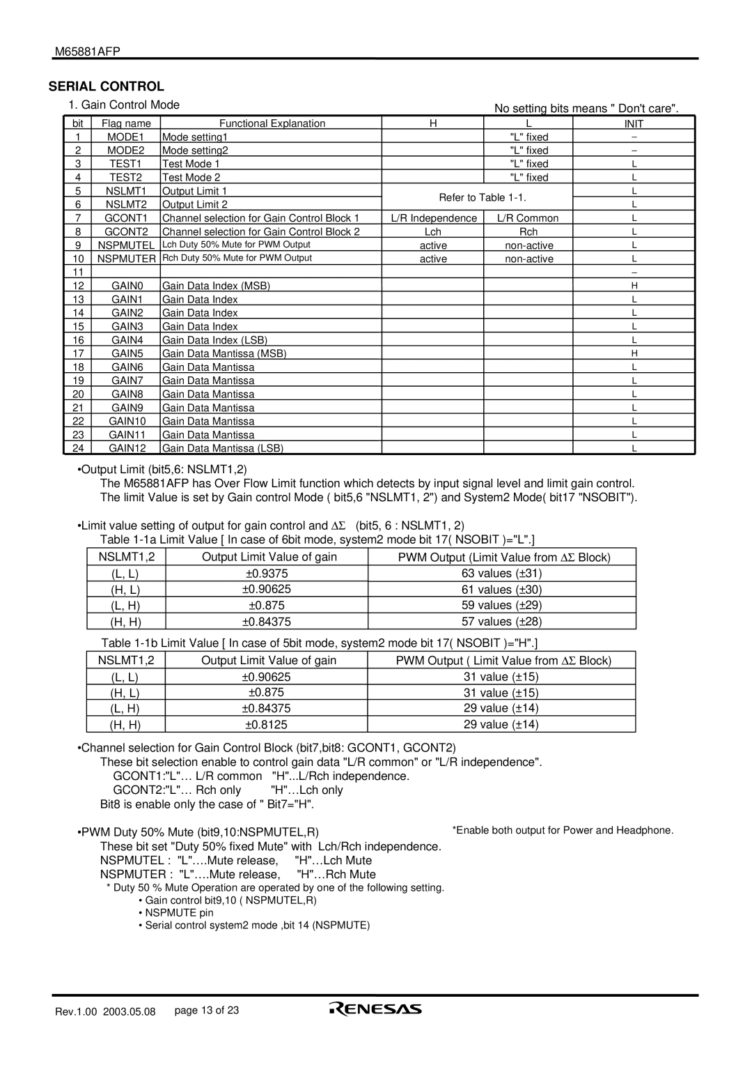
•Output Limit (bit5,6: NSLMT1,2)
The M65881AFP has Over Flow Limit function which detects by input signal level and limit gain control. The limit Value is set by Gain control Mode ( bit5,6 "NSLMT1, 2") and System2 Mode( bit17 "NSOBIT").
•Limit value setting of output for gain control and ΔΣ | (bit5, 6 : NSLMT1, 2) | |||||
|
| Table | ||||
|
| NSLMT1,2 |
| Output Limit Value of gain |
| PWM Output (Limit Value from ΔΣ Block) |
|
|
|
|
|
|
|
|
| (L, L) |
| ±0.9375 |
| 63 values (±31) |
|
| (H, L) |
| ±0.90625 |
| 61 values (±30) |
|
| (L, H) |
| ±0.875 |
| 59 values (±29) |
|
| (H, H) |
| ±0.84375 |
| 57 values (±28) |
|
| Table | ||||
| NSLMT1,2 | Output Limit Value of gain |
| PWM Output ( Limit Value from ΔΣ Block) | ||
|
| (L, L) | ±0.90625 |
| 31 value (±15) | |
|
| (H, L) | ±0.875 |
| 31 value (±15) | |
|
| (L, H) | ±0.84375 |
| 29 value (±14) | |
|
| (H, H) | ±0.8125 |
| 29 value (±14) | |
•Channel selection for Gain Control Block (bit7,bit8: GCONT1, GCONT2)
These bit selection enable to control gain data "L/R common" or "L/R independence".
GCONT1:"L"… L/R common | "H"...L/Rch independence. |
| |
GCONT2:"L"… Rch only | "H"…Lch only |
| |
Bit8 is enable only the case of " Bit7="H". |
| ||
•PWM Duty 50% Mute (bit9,10:NSPMUTEL,R) | *Enable both output for Power and Headphone. | ||
These bit set "Duty 50% fixed Mute" with Lch/Rch independence. |
| ||
NSPMUTEL : "L"….Mute release, | "H"…Lch Mute |
| |
NSPMUTER : "L"….Mute release, | "H"…Rch Mute |
| |
*Duty 50 % Mute Operation are operated by one of the following setting.
•Gain control bit9,10 ( NSPMUTEL,R)
•NSPMUTE pin
•Serial control system2 mode ,bit 14 (NSPMUTE)
Rev.1.00 2003.05.08 | page 13 of 23 |
