| M65881AFP |
|
|
|
|
|
|
|
|
|
|
|
|
|
|
|
|
|
|
|
|
|
|
| |||||
|
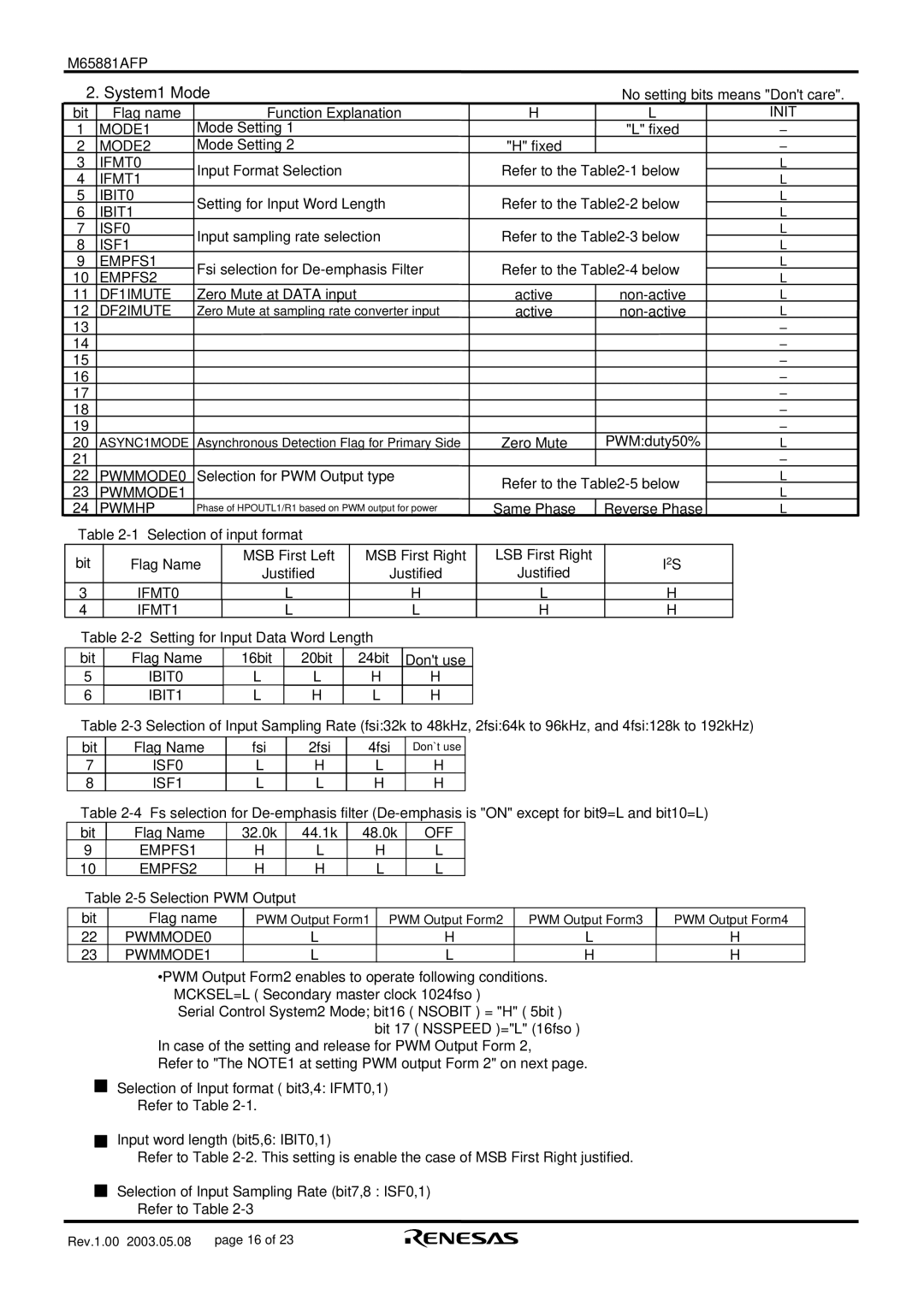
| 2. System1 Mode |
|
|
|
|
|
|
|
|
|
|
|
|
|
|
|
|
| No setting bits means "Don't care". | |||||||||
| bit |
| Flag name |
|
|
| Function Explanation |
|
|
|
|
| H |
| L | INIT | |||||||||||||
| 1 |
| MODE1 | Mode Setting 1 |
|
|
|
|
|
|
|
|
|
|
|
|
|
| "L" fixed | – | |||||||||
| 2 |
| MODE2 | Mode Setting 2 |
|
|
|
|
|
|
|
|
|
| "H" fixed |
|
|
|
| – | |||||||||
| 3 |
| IFMT0 | Input Format Selection |
|
|
|
|
|
| Refer to the | L | |||||||||||||||||
| 4 |
| IFMT1 |
|
|
|
|
|
| L | |||||||||||||||||||
|
|
|
|
|
|
|
|
|
|
|
|
|
|
|
|
|
|
|
|
|
|
|
| ||||||
| 5 |
| IBIT0 | Setting for Input Word Length |
|
|
|
| Refer to the | L | |||||||||||||||||||
| 6 |
| IBIT1 |
|
|
|
| L | |||||||||||||||||||||
|
|
|
|
|
|
|
|
|
|
|
|
|
|
|
|
|
|
|
|
|
|
|
| ||||||
| 7 |
| ISF0 | Input sampling rate selection |
|
|
|
| Refer to the | L | |||||||||||||||||||
| 8 |
| ISF1 |
|
|
|
| L | |||||||||||||||||||||
|
|
|
|
|
|
|
|
|
|
|
|
|
|
|
|
|
|
|
|
|
|
|
| ||||||
| 9 |
| EMPFS1 | Fsi selection for |
|
| Refer to the | L | |||||||||||||||||||||
| 10 |
| EMPFS2 |
|
| L | |||||||||||||||||||||||
|
|
|
|
|
|
|
|
|
|
|
|
|
|
|
|
|
|
|
|
|
|
|
| ||||||
| 11 |
| DF1IMUTE | Zero Mute at DATA input |
|
|
|
|
|
| active |
| L | ||||||||||||||||
| 12 |
| DF2IMUTE | Zero Mute at sampling rate converter input |
|
| active |
| L | ||||||||||||||||||||
| 13 |
|
|
|
|
|
|
|
|
|
|
|
|
|
|
|
|
|
|
|
|
|
|
|
|
|
| – | |
| 14 |
|
|
|
|
|
|
|
|
|
|
|
|
|
|
|
|
|
|
|
|
|
|
|
|
|
| – | |
| 15 |
|
|
|
|
|
|
|
|
|
|
|
|
|
|
|
|
|
|
|
|
|
|
|
|
|
| – | |
| 16 |
|
|
|
|
|
|
|
|
|
|
|
|
|
|
|
|
|
|
|
|
|
|
|
|
|
| – | |
| 17 |
|
|
|
|
|
|
|
|
|
|
|
|
|
|
|
|
|
|
|
|
|
|
|
|
|
| – | |
| 18 |
|
|
|
|
|
|
|
|
|
|
|
|
|
|
|
|
|
|
|
|
|
|
|
|
|
| – | |
| 19 |
|
|
|
|
|
|
|
|
|
|
|
|
|
|
|
|
|
|
|
|
|
|
| PWM:duty50% | – | |||
| 20 |
| ASYNC1MODE | Asynchronous Detection Flag for Primary Side |
|
| Zero Mute |
| L | ||||||||||||||||||||
| 21 |
|
|
|
|
|
|
|
|
|
|
|
|
|
|
|
|
|
|
|
|
|
|
|
|
|
| – | |
| 22 |
| PWMMODE0 | Selection for PWM Output type |
|
|
|
| Refer to the | L | |||||||||||||||||||
| 23 |
| PWMMODE1 |
|
|
|
|
|
|
|
|
|
|
|
|
|
|
| L | ||||||||||
|
|
|
|
|
|
|
|
|
|
|
|
|
|
|
|
|
|
|
|
|
|
|
| ||||||
| 24 |
| PWMHP | Phase of HPOUTL1/R1 based on PWM output for power |
| Same Phase | Reverse Phase | L | |||||||||||||||||||||
|
| Table |
|
|
|
|
|
|
|
|
|
|
|
|
|
| |||||||||||||
|
|
|
|
|
|
|
|
| MSB First Left |
|
| MSB First Right |
|
| LSB First Right |
|
|
|
|
| |||||||||
|
| bit |
|
|
| Flag Name |
|
|
| I2S |
|
| |||||||||||||||||
|
|
|
|
|
|
| Justified |
|
|
|
| Justified |
|
|
|
| Justified |
|
|
|
|
| |||||||
|
|
|
|
|
|
|
|
|
|
|
|
|
|
|
|
|
|
|
|
|
|
| |||||||
| 3 |
|
|
| IFMT0 |
|
|
|
| L |
|
|
|
|
|
| H |
|
|
| L |
|
| H |
| ||||
|
|
|
|
|
|
|
|
|
|
|
|
|
|
|
|
|
|
|
| ||||||||||
| 4 |
|
|
| IFMT1 |
|
|
|
| L |
|
|
|
|
|
| L |
|
|
| H |
|
| H |
| ||||
|
| Table |
|
|
|
|
|
|
|
|
|
|
|
| |||||||||||||||
|
| bit |
|
| Flag Name | 16bit |
| 20bit |
|
| 24bit | Don't use |
|
|
|
|
|
|
|
|
|
| |||||||
| 5 |
|
| IBIT0 |
|
| L |
| L |
|
| H | H |
|
|
|
|
|
|
|
|
|
| ||||||
| 6 |
|
| IBIT1 |
|
| L |
|
| H |
|
| L | H |
|
|
|
|
|
|
|
|
|
| |||||
Table
bit | Flag Name | fsi | 2fsi | 4fsi | Don`t use |
7 | ISF0 | L | H | L | H |
8 | ISF1 | L | L | H | H |
Table
| bit | Flag Name | 32.0k |
| 44.1k | 48.0k | OFF |
|
|
| ||
| 9 | EMPFS1 |
| H |
| L | H | L |
|
|
| |
| 10 | EMPFS2 |
| H |
| H |
| L | L |
|
|
|
| Table |
|
|
|
|
|
|
| ||||
|
|
|
|
|
|
|
| |||||
| bit | Flag name |
| PWM Output Form1 | PWM Output Form2 | PWM Output Form3 | PWM Output Form4 | |||||
| 22 | PWMMODE0 |
|
|
| L |
|
| H | L | H | |
| 23 | PWMMODE1 |
|
|
| L |
|
| L | H | H | |
•PWM Output Form2 enables to operate following conditions. MCKSEL=L ( Secondary master clock 1024fso )
Serial Control System2 Mode; bit16 ( NSOBIT ) = "H" ( 5bit ) bit 17 ( NSSPEED )="L" (16fso )
In case of the setting and release for PWM Output Form 2,
Refer to "The NOTE1 at setting PWM output Form 2" on next page.
Selection of Input format ( bit3,4: IFMT0,1)
Refer to Table
Input word length (bit5,6: IBIT0,1)
Refer to Table
Selection of Input Sampling Rate (bit7,8 : ISF0,1)
Refer to Table
Rev.1.00 2003.05.08 | page 16 of 23 |