M65881AFP
2. SCDT, SCSHIFT, SCLATCH
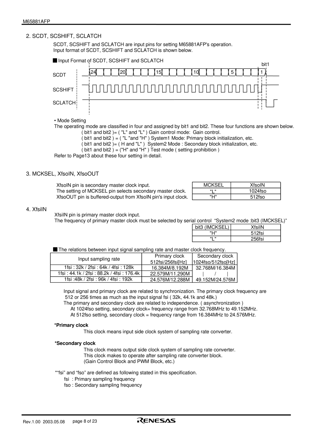
SCDT, SCSHIFT and SCLATCH are input pins for setting M65881AFP's operation.
Input format of SCDT, SCSHIFT and SCLATCH is shown below.
![]()
![]() Input Format of SCDT, SCSHIFT and SCLATCH
Input Format of SCDT, SCSHIFT and SCLATCH
bit1
SCDT | 24 | 20 | 15 | 10 | 5 | 1 |
|
|
|
|
|
|
SCSHIFT
SCLATCH 
• Mode Setting
The operating mode are classified in four and assigned by bit1 and bit2. These four functions are shown below. ( bit1 and bit2 )= ( "L" and "L" ) Gain control mode: Gain control.
( bit1 and bit2 ) = ( "L "and "H" ) System1 Mode: Primary block initialization, etc.
( bit1 and bit2 )= ( H and "L" ) System2 Mode : Secondary block initialization, etc. ( bit1 and bit2 ) = ("H" and "H" ) Test mode ( setting prohibition )
Refer to Page13 about these four setting in detail.
3. MCKSEL, XfsoIN, XfsoOUT
XfsoIN pin is secondary master clock input.
The setting of MCKSEL pin selects secondary master clock. XfsoOUT pin is
MCKSEL | XfsoIN |
"L" | 1024fso |
"H" | 512fso |
4. XfsiIN
XfsiIN pin is primary master clock input.
The frequency of primary master clock must be selected by serial control “System2 mode :bit3 (IMCKSEL)”
bit3 (IMCKSEL) | XfsiIN |
"H" | 512fsi |
"L" | 256fsi |
![]()
![]() The relations between input signal sampling rate and master clock frequency.
The relations between input signal sampling rate and master clock frequency.
Input sampling rate | Primary clock | Secondary clock | |||
512fsi/256fsi[Hz] | 1024fso/512fso[Hz] | ||||
| |||||
1fsi : 32k / 2fsi : 64k / 4fsi : 128k | 16.384M/8.192M | 32.768M/16.384M | |||
1fsi : 44.1k / 2fsi : 88.2k / 4fsi : 176.4k | 22.579M/11.290M | / | |||
1fsi :48k / 2fsi : 96k / 4fsi : 192k | 24.576M/12.288M | 49.152M/24.576M | |||
Input signal and primary clock are related to synchronization. The primary clock frequency are 512 or 256 times as much as the input signal fsi ( 32k, 44.1k and 48k.)
The primary and secondary clock are related to independence. ( asynchronization )
At 1024fso setting, secondary clock= frequency range from 32.768MHz to 49.152MHz. At 512fso setting, secondary clock = frequency range from 16.384MHz to 24.576MHz.
*Primary clock
This clock means input side clock system of sampling rate converter.
*Secondary clock
This clock means output side clock system of sampling rate converter. This clock makes to operate after sampling rate converter block. (Gain Control Block and PWM Block, etc.)
*“fsi” and “fso” are defined as following stated in this specification. fsi : Primary sampling frequency
fso : Secondary sampling frequency
Rev.1.00 2003.05.08 | page 8 of 23 |