No. 700 Portable Power Drive
2.Pull knobs (Figure 7) of cam plate and rotate cam plate to desired pipe size marking on top of die head. Release knobs when locating pins drop into holes in selector plate.
No. 844
Drive Bar
Drive Shaft
Set Screws
Cam
Plate Knob
Cam
Plate KnobClamp
Screw
Figure 7 – No 141 Geared Threader (No. 161 Threader Similar)
Thread Size Adjustment Procedure
Grasp workholder and turn square end of drive shaft or turn gear case by hand to respective reference lines on guide post (Figure 8).
Standard Size Thread – Either one of the following two (2) reference lines may be used.
Reference Line 1: Set bottom surface of die head at red STANDARD line on pinion sleeve.
Reference Line 2: Set upper surface of die head which houses guide post even with STANDARD line at top end of guide post.
Oversize Thread: For oversize (shallow thread) set head at bottom line on guide post. This line is marked (2T OVER).
Undersize Thread: For undersize (deep throat) set head at top line on guide post. This line is marked (2T UNDER).
Changing posts For Straight Or Tapered Threads
(Figure 8)
1.Adjust threader to cut standard size threads using “STANDARD” reference line.
2.Remove screw from gear case at base of guide post.
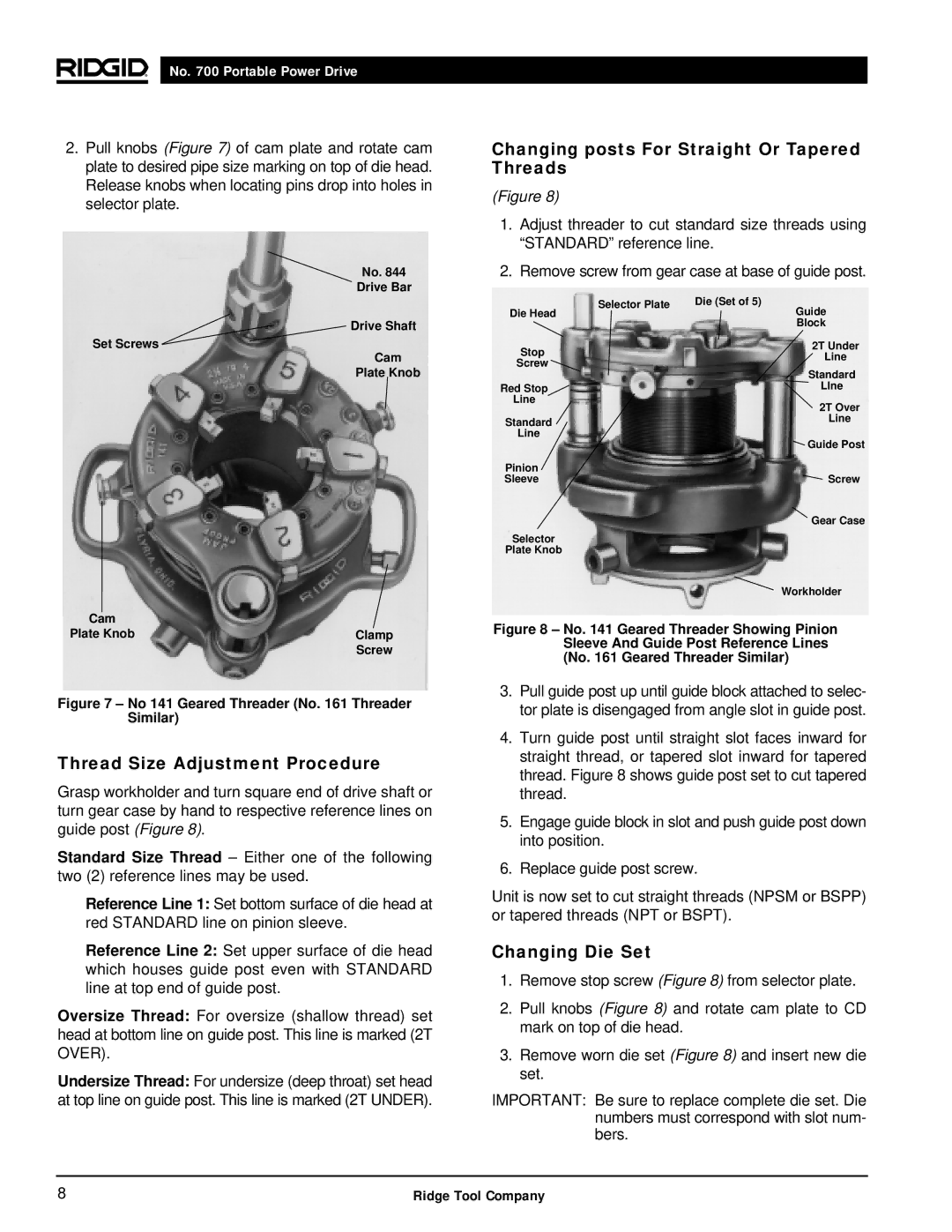
Selector Plate | Die (Set of 5) |
Die Head | Guide |
| Block |
2T Under
StopLine
Screw
Standard
Red StopLIne
Line
2T Over
StandardLine
Line
| Guide Post |
Pinion |
|
Sleeve | Screw |
| Gear Case |
Selector |
|
Plate Knob |
|
| Workholder |
Figure 8 – No. 141 Geared Threader Showing Pinion Sleeve And Guide Post Reference Lines (No. 161 Geared Threader Similar)
3.Pull guide post up until guide block attached to selec- tor plate is disengaged from angle slot in guide post.
4.Turn guide post until straight slot faces inward for straight thread, or tapered slot inward for tapered thread. Figure 8 shows guide post set to cut tapered thread.
5.Engage guide block in slot and push guide post down into position.
6.Replace guide post screw.
Unit is now set to cut straight threads (NPSM or BSPP) or tapered threads (NPT or BSPT).
Changing Die Set
1.Remove stop screw (Figure 8) from selector plate.
2.Pull knobs (Figure 8) and rotate cam plate to CD mark on top of die head.
3.Remove worn die set (Figure 8) and insert new die set.
IMPORTANT: Be sure to replace complete die set. Die numbers must correspond with slot num- bers.
8 | Ridge Tool Company |