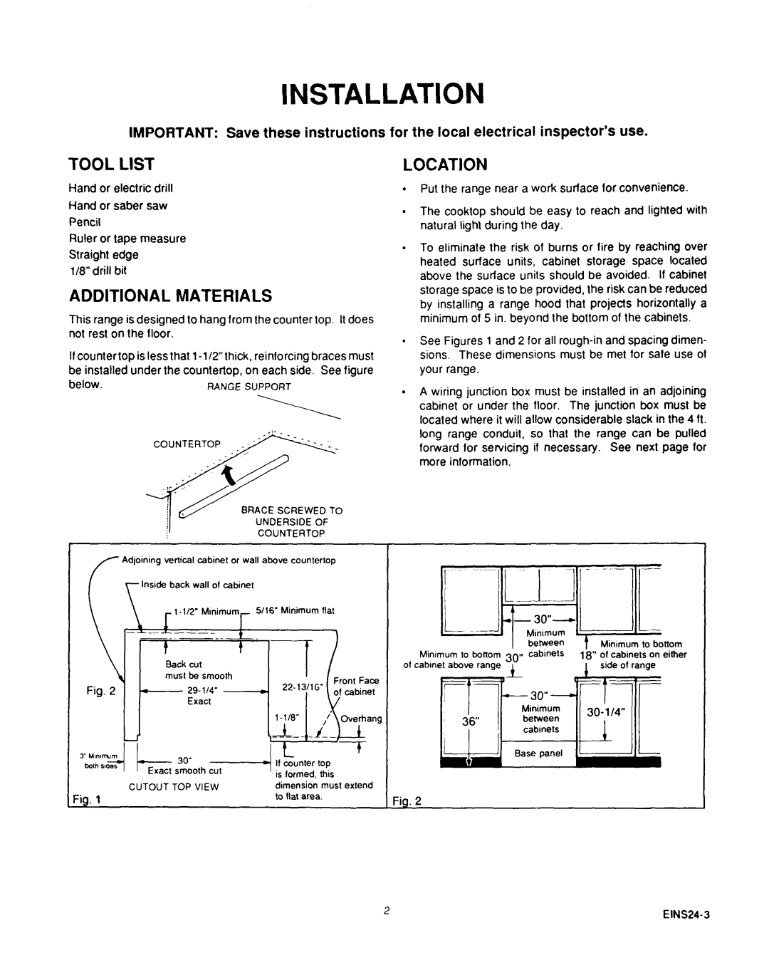
D975 specifications
The Roper D975 is a standout in the realm of heavy machinery, particularly designed for agricultural and industrial applications. Its robust construction and innovative features make it an ideal choice for professionals seeking reliability and efficiency in demanding environments.One of the key features of the Roper D975 is its powerful engine, delivering exceptional horsepower and torque. This enables the machine to tackle a variety of tasks, from plowing fields to lifting heavy loads. The engine is not only powerful but also designed for fuel efficiency, allowing operators to work longer while reducing operational costs.
Another significant characteristic of the Roper D975 is its advanced hydraulic system. This system provides superior lift capabilities, essential for tasks that require precise movement of heavy materials or equipment. The hydraulic system is responsive and efficient, ensuring that operators can execute tasks smoothly without any lag.
The D975 is equipped with an intuitive operator interface, featuring ergonomic controls and displays that provide real-time feedback on the machine’s performance. This user-friendly design ensures that operators can navigate the machine effectively, maximizing productivity and reducing the chance of errors.
In terms of durability, the Roper D975 features a rugged frame constructed from high-quality materials, allowing it to withstand harsh working conditions. The machine also has a reinforced undercarriage and reinforced axles, contributing to its ability to handle rough terrains without compromising stability.
Safety is a top priority with the Roper D975, which includes numerous safety features such as rollover protection structures (ROPS) and safety alarms. These features ensure that operators can work confidently, knowing that their well-being is safeguarded.
Moreover, the D975 is compatible with a range of attachments, enhancing its versatility. This adaptability allows users to customize the machine for specific jobs, whether it involves grading land, excavating, or performing agricultural tasks.
In summary, the Roper D975 combines power, efficiency, and versatility in one reliable package. Its advanced technologies, durable construction, and focus on operator safety make it a valuable asset for anyone in need of a heavy-duty machine. Whether for agricultural purposes or industrial use, the Roper D975 stands out as a true workhorse in its category.

