Rotel RB-1510 Speaker Connections, Signal Output Link Connectors, Speaker Selection, English

Models: RB-1510

1 51
Download 51 pages 61.56 Kb
Page 9
Image 9
Signal Output Link Connectors 6

English

9

Signal Output Link Connectors 6

The input signal that goes into the normal Inputs 5 also goes to the Signal Output Link 6 connectors. This is typically used when the amplifier is part of a multi-room system. The signal from the Signal Output Link is then used to provide a signal to the other amplifiers in the system.

Speaker Connections

Speaker Selection

We recommend using loudspeakers with a nominal impedance of 4 ohms or higher with the RB-1510. You should exercise some caution in driving multiple pairs of speakers in parallel configuration, because the effective impedance the amplifier sees is cut in half. For example, when driving two pair of 8 ohm speakers, the amplifier sees a 4 ohm load. When driving multiple speakers in parallel, it is recommended that you select speakers with a nominal impedance of 8 ohms or higher. Speaker impedance ratings are less than precise. In practice, very few loudspeakers will present any problems for the RB-1510. See your authorized Rotel dealer if you have any questions.

Speaker Wire Selection

Use insulated two-conductor stranded wire to connect the RB-1510 to the speakers. The size and quality of the wire can have an audible effect on the performance of the system. Standard speaker wire will work, but can result in lower output or diminished bass response, particularly over longer distances. In general, heavier wire will improve the sound. For best performance, you may want to consider special high-quality speaker cables. Your authorized Rotel dealer can help in the selection of appropriate cables for your system.

Polarity and Phasing

The polarity — the positive/negative orientation of the connections

for every speaker and amplifier connection must be consistent so all the speakers will be in phase. If the polarity of one connection is mistakenly reversed, bass output will be very weak and stereo imaging degraded. All wire is marked so you can identify the two conductors. There may be ribs or a stripe on the insulation of one conductor. The wire may have clear insulation with different color conductors (copper and silver). There may be polarity indications printed on the insulation. Identify the positive and negative conductors and be consistent with every speaker and amplifier connection.

Speaker Wire Connection

Route the wire from the RB-1510 to the speakers. Give yourself enough slack so you can move the components enough to allow access to the speaker connectors.

The RB-1510 has two pairs of color coded binding posts 9 on the back panel. These connectors accept bare wire, connector lugs, or dual banana type connectors (except in the European Community countries where their use is not permitted).

The RB-1510 also has a plug-in speaker connector 0 that can make connection easier in custom installations. You can pre-wire the plug-in connector before the amplifier is installed. The plug-in connector is wires in parallel with the bind post outputs.

Note: The following text describes both binding post and plug-in connections. DO NOT use both connection methods in combination to connect multiple speakers.

Binding Post Connection 9

If you are using banana plugs, connect them to the wires and then plug into the backs of the speaker connectors. The collars of the speaker connectors should be screwed in all the way (clockwise).

If you are using terminal lugs, connect them to the wires. If you are attaching bare wires directly to the speaker connectors, separate the wire conductors and strip back the insulation from the end of each conductor. Be careful not to cut into the wire strands. Unscrew (turn counterclockwise) the speaker connector collar. Place the connector lug around the shaft, or insert the bundled wire into the hole in the shaft. Turn the collars clockwise to clamp the connector lug or wire firmly in place.

Note: Be sure there are no loose wire strands that could touch adjacent wires or connectors.

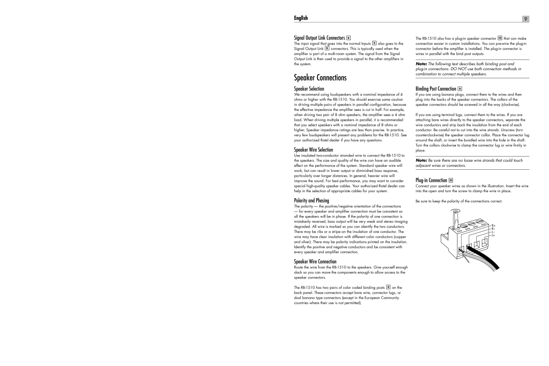
Plug-in Connection 0

Connect your speaker wires as shown in the illustration. Insert the wire into the open and turn the screw to clamp the wire in place.

Be sure to keep the polarity of the connections correct.

R+

R–

L–

Speaker ConnectionsL+

Page 9
Image 9
Rotel RB-1510 Speaker Connections, Signal Output Link Connectors, Speaker Selection, Speaker Wire Selection, English