Appendix A
Internal Access
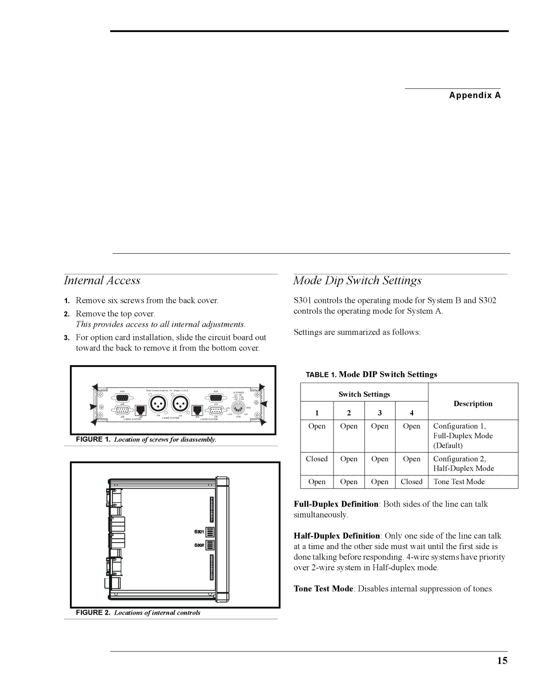
1.Remove six screws from the back cover.
2.Remove the top cover.
This provides access to all internal adjustments.
3.For option card installation, slide the circuit board out toward the back to remove it from the bottom cover.
AUX | Telex Communications, Inc., Made in U.S.A. |
| AUX | J5 POWER | ||
|
|
|
|
| ||
|
|
|
|
| +5V 3A | |
|
|
|
|
| +15V | 1.6A |
|
|
|
|
| ||
J4B |
|
|
| J4A |
|
|
|
|
|
| +5V |
| RTN |
| J1B | J1A |
| +15V |
| |
J3B | J2B | 2 WIRE SYSTEM | J2A | J3A | RTN | |
4 WIRE SYSTEM |
|
| 4 WIRE SYSTEM |
|
| |
FIGURE 1. Location of screws for disassembly.
Mode Dip Switch Settings
S301 controls the operating mode for System B and S302 controls the operating mode for System A.
Settings are summarized as follows:
TABLE 1. Mode DIP Switch Settings
| Switch Settings |
| Description | ||
|
|
|
| ||
1 | 2 | 3 | 4 | ||
| |||||
|
|
|
|
| |
Open | Open | Open | Open | Configuration 1, | |
|
|
|
| ||
|
|
|
| (Default) | |
|
|
|
|
| |
Closed | Open | Open | Open | Configuration 2, | |
|
|
|
| ||
|
|
|
|
| |
Open | Open | Open | Closed | Tone Test Mode | |
|
|
|
|
| |
Tone Test Mode: Disables internal suppression of tones.
FIGURE 2. Locations of internal controls
15