4-Wire Call Signal Connections
TABLE 3. UIO-256 GPI Outputs Connector (J5)
| | GPI OUTPUT NUMBERSa | | RELAY CONTACT PIN NUMBERS |
| | | | | | NORMAL | | NORMAL |
| UIO-256 | UIO-256 | UIO-256 | UIO-256 | CLOSED (NC) | COMMON | OPEN (NO) |
| FRAME #1 | FRAME #2 | FRAME #3 | FRAME #4 | CONTACT | CONTACT | CONTACT |
| | | | | | | | |
15 | 31 | | 47 | 63 | 35 | 10 | 37 |
| | | | | | | | |
16 | 32 | | 48 | 64 | 36 | 11 | 12 |
| | | | | | | | |
| | | | | | | | |
a. Dependent on UIO-256 DIP Switch SW1 Settings for Input/Output Range as summarized in the UIO-256 manual.
Call Signal Connections for other 4-wire
Communications Systems
4-wire Call Send and Call Enable/Inhibit
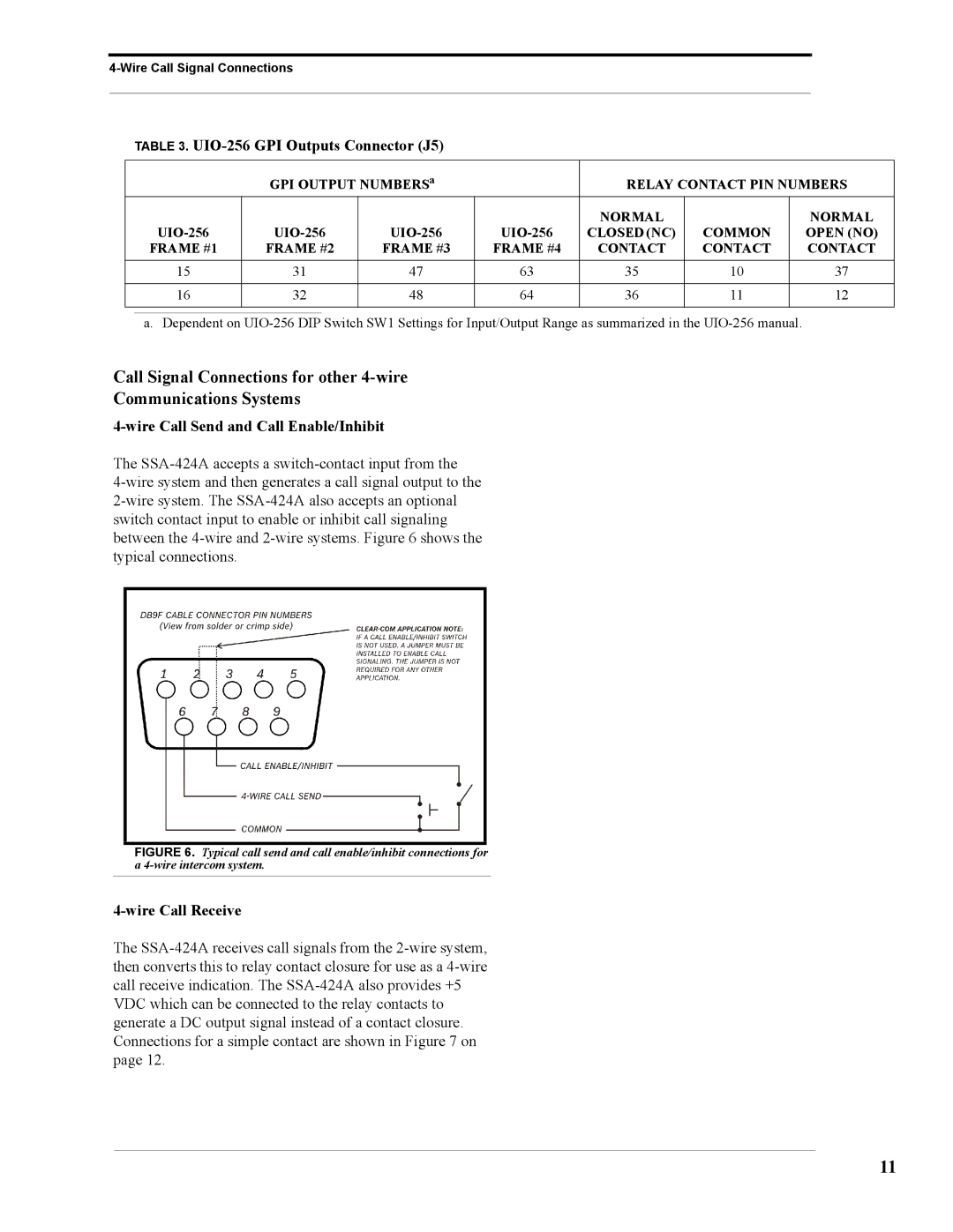
The SSA-424A accepts a switch-contact input from the
4-wire system and then generates a call signal output to the 2-wire system. The SSA-424A also accepts an optional switch contact input to enable or inhibit call signaling between the 4-wire and 2-wire systems. Figure 6 shows the typical connections.
FIGURE 6. Typical call send and call enable/inhibit connections for a 4-wire intercom system.
4-wire Call Receive
The SSA-424A receives call signals from the 2-wire system, then converts this to relay contact closure for use as a 4-wire call receive indication. The SSA-424A also provides +5 VDC which can be connected to the relay contacts to generate a DC output signal instead of a contact closure. Connections for a simple contact are shown in Figure 7 on page 12.