Description and Specifications
LEVEL | | | SYSTEM A | | |
SET | | | | | |
| | | | | | | | |
| | | | | | | | | | | |
| -15 | -12 | -9 | -6 -3 | 0 +3 +6 | +9 | +12 |
| | | | | | | | | | | |
| | | | +4dB | | 2 | | | 2W CHAN SEL |
| | | 0dB | +8dB | 1 | | BAL | | |
| | | -10dB | | +12dB | OFF | | OFF | | |
| | | | 4W LEVEL | | 1 | 2 | BAL |
POWER | | | | | | |
| | | | REF SEL | | | | | | |
LEVEL | | | | SYSTEM B | | | |
SET | | | | | | | | | | | | |
TO | | | | | | | | | | | | TO |
4W | | | | | | | | | | | | 4W |
-15 -12 | -9 | | -6 -3 | 0 +3 +6 | +9 | +12 | |
TO | | | | | | | | | | | | TO |
2W | | | | | | | | | | | | 2W |
| | +4dB | +8dB | 2 | | | 2W CHAN SEL | |
| 0dB | 1 | BAL | | | |
| -10dB | +12dB | OFF | OFF | | | |
| | | | | | | 1 | 2 | BAL |
| | 4W LEVEL | | | | | | SSA-424A |
| | REF SEL | | | | | |
| AUX | Telex Communications, Inc., Made in U.S.A. |
| J4B | | |
| J3B | J1B | J1A |
| J2B | 2 WIRE SYSTEM |
| 4 WIRE SYSTEM |
| |
AUX | J5 POWER |
| +5V | 3A |
| +15V | 1.6A |
| -15V 0.3A |
J4A
| +5V | RTN |
| +15V | -15V |
J2A | J3A | RTN |
| 4 WIRE SYSTEM | |
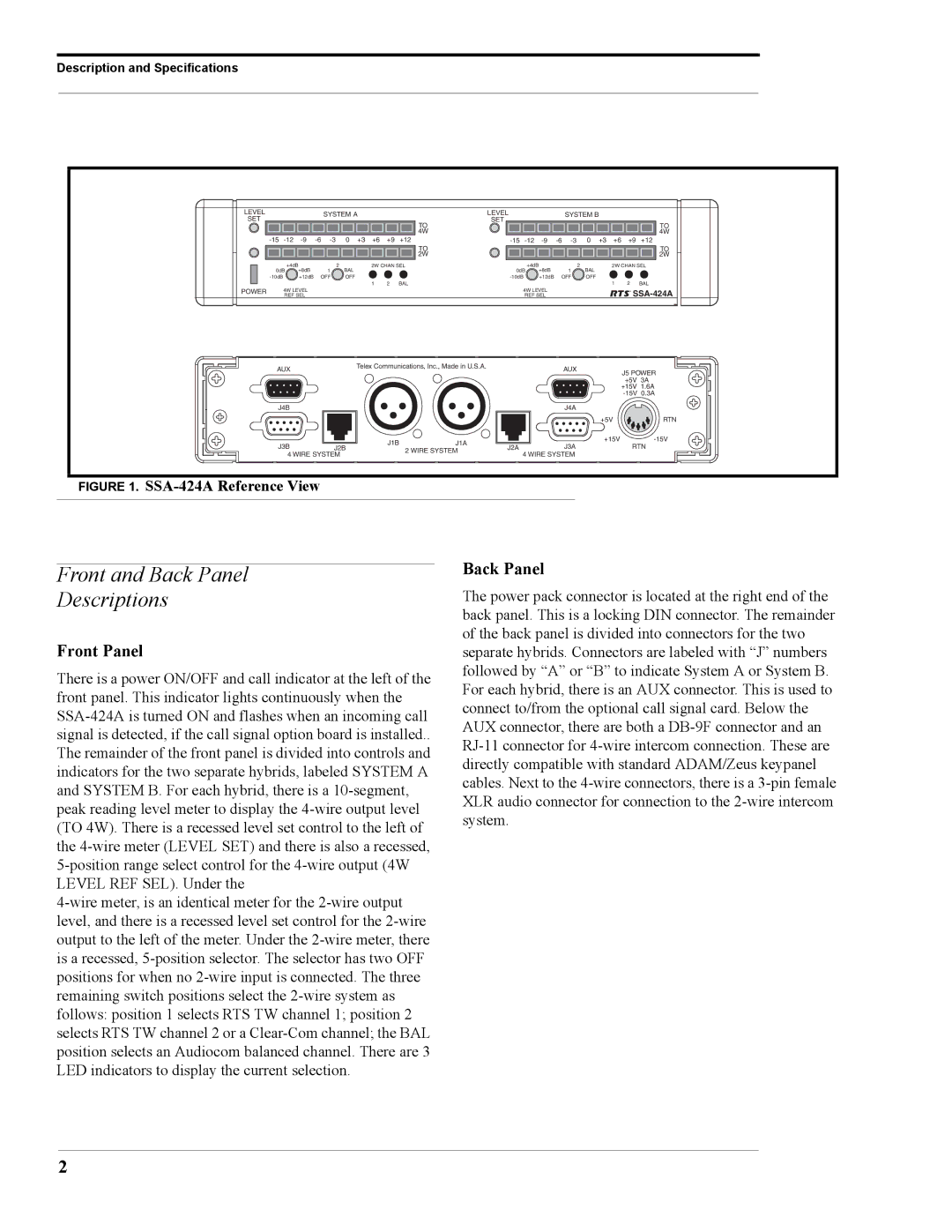
FIGURE 1. SSA-424A Reference View
Front and Back Panel
Descriptions
Front Panel
There is a power ON/OFF and call indicator at the left of the front panel. This indicator lights continuously when the SSA-424A is turned ON and flashes when an incoming call signal is detected, if the call signal option board is installed.. The remainder of the front panel is divided into controls and indicators for the two separate hybrids, labeled SYSTEM A and SYSTEM B. For each hybrid, there is a 10-segment, peak reading level meter to display the 4-wire output level (TO 4W). There is a recessed level set control to the left of the 4-wire meter (LEVEL SET) and there is also a recessed, 5-position range select control for the 4-wire output (4W LEVEL REF SEL). Under the
4-wire meter, is an identical meter for the 2-wire output level, and there is a recessed level set control for the 2-wire output to the left of the meter. Under the 2-wire meter, there is a recessed, 5-position selector. The selector has two OFF positions for when no 2-wire input is connected. The three remaining switch positions select the 2-wire system as follows: position 1 selects RTS TW channel 1; position 2 selects RTS TW channel 2 or a Clear-Com channel; the BAL position selects an Audiocom balanced channel. There are 3 LED indicators to display the current selection.
Back Panel
The power pack connector is located at the right end of the back panel. This is a locking DIN connector. The remainder of the back panel is divided into connectors for the two separate hybrids. Connectors are labeled with “J” numbers followed by “A” or “B” to indicate System A or System B. For each hybrid, there is an AUX connector. This is used to connect to/from the optional call signal card. Below the AUX connector, there are both a DB-9F connector and an RJ-11 connector for 4-wire intercom connection. These are directly compatible with standard ADAM/Zeus keypanel cables. Next to the 4-wire connectors, there is a 3-pin female XLR audio connector for connection to the 2-wire intercom system.