NOTE: The
2.On the
NOTE: If the System A or System B will not be used, set the 2W CHAN SEL switch to the OFF position and attach a dummy load to the TW XLR connector.
TW CABLE |
|
|
| |
PIN 1 COMMON | FROM RTS TW | |||
PIN 2 CH 1 | ||||
INTERCOM SYSTEM | ||||
PIN 3 CH 2 | ||||
|
|
| ||
|
|
| ||
PUSH |
|
| AUX |
| Telex Communications, Inc., Made in U.S.A. |
| AUX | J5 POWER | ||
|
|
|
|
|
|
| +5V 3A | |
|
|
|
|
|
| +15V | 1.6A | |
|
|
|
|
|
| |||
J4B |
|
|
|
| +5V |
| RTN | |
|
|
|
|
| J4A |
|
| |
|
|
| J1B | J1A |
| +15V |
| |
| J3B | J2B |
| 2 WIRE SYSTEM | J2A | J3A | RTN | |
| 4 WIRE SYSTEM |
|
| 4 WIRE SYSTEM |
|
| ||
FIGURE 3. Using a TW-5W to connect to two TW channels to the SSA-424A
Audiocom Audio Connection
1.You can directly connect standard Audio
NOTE: The
2.On the
NOTE: If System A or System B hybrid will not be used, set the 2W CHAN SEL switch to the OFF position and attach a dummy load to the TW XLR connector.
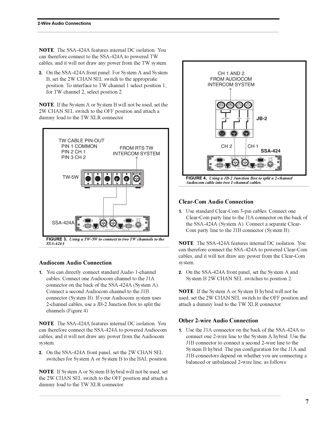
CH 1 AND 2
FROM AUDIOCOM
INTERCOM SYSTEM
|
|
|
|
|
|
|
|
|
|
| |
|
|
|
|
|
|
|
|
|
|
| |
|
|
|
|
|
|
|
|
|
|
| |
|
|
|
|
|
|
|
|
|
|
| |
|
|
|
|
|
|
|
|
|
|
| |
|
|
|
|
|
|
|
|
|
|
| |
| 1&2 LINES |
|
| 2 LINE |
| 1 LINE |
| ||||
|
|
|
|
|
|
|
|
|
|
|
|
|
|
|
|
|
|
|
|
|
|
|
|
|
|
|
|
|
|
|
|
|
|
|
|
CH 2 | CH 1 |
SSA-424
AUX |
| Telex Communications, Inc., Made in U.S.A. |
| AUX | J5 POWER | ||
|
|
|
|
|
| +5V 3A | |
|
|
|
|
|
| +15V | 1.6A |
|
|
|
|
|
| ||
J4B |
|
|
|
| J4A |
|
|
|
|
|
|
| +5V |
| RTN |
|
| J1B | J1A |
| +15V |
| |
J3B | J2B |
| 2 WIRE SYSTEM | J2A | J3A | RTN | |
4 WIRE SYSTEM |
|
| 4 WIRE SYSTEM |
|
| ||
FIGURE 4. Using a JB-2 Junction Box to split a 2-channel Audiocom cable into two 1-channel cables.
Clear-Com Audio Connection
1.Use standard
NOTE: The
2.On the
NOTE: If the System A or System B hybrid will not be used, set the 2W CHAN SEL switch to the OFF position and attach a dummy load to the TW XLR connector.
Other 2-wire Audio Connection
1.Use the J1A connector on the back of the
balanced or unbalanced
7