User Manual
4-4-5. Logout
Besides the auto logout function as we mentioned above in the section of system configuration, the switch also allows the user to logout manually by performing the Logout function.
Function name:
Logout
Function description:
The switch allows you to logout the system to prevent other users from the system without the permission. If you do not logout and exit the browser, the switch will automatically have you logout. Besides this manually logout and implicit logout, you can set up the parameter of Auto Logout Timer in system configuration function to explicitly ON/OFF this logout function.
Parameter description:
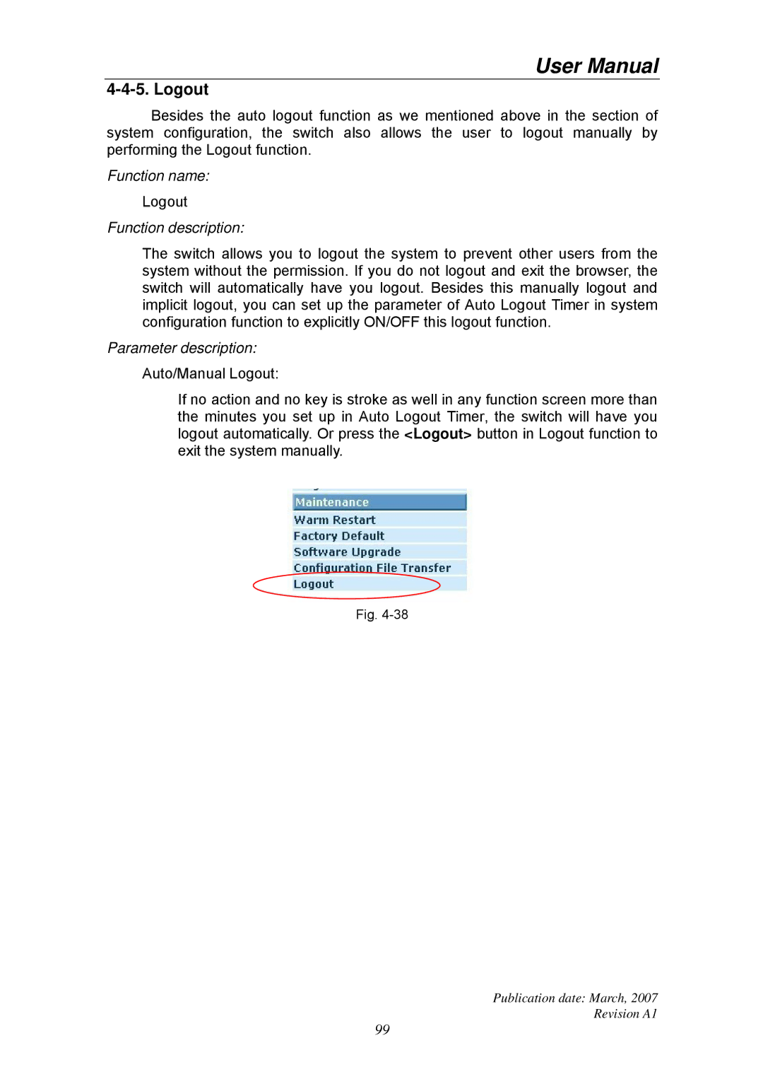
Auto/Manual Logout:
If no action and no key is stroke as well in any function screen more than the minutes you set up in Auto Logout Timer, the switch will have you logout automatically. Or press the <Logout> button in Logout function to exit the system manually.
Fig.
Publication date: March, 2007
Revision A1
99