3. Installation Procedures
3.4.2. Pole Mounting
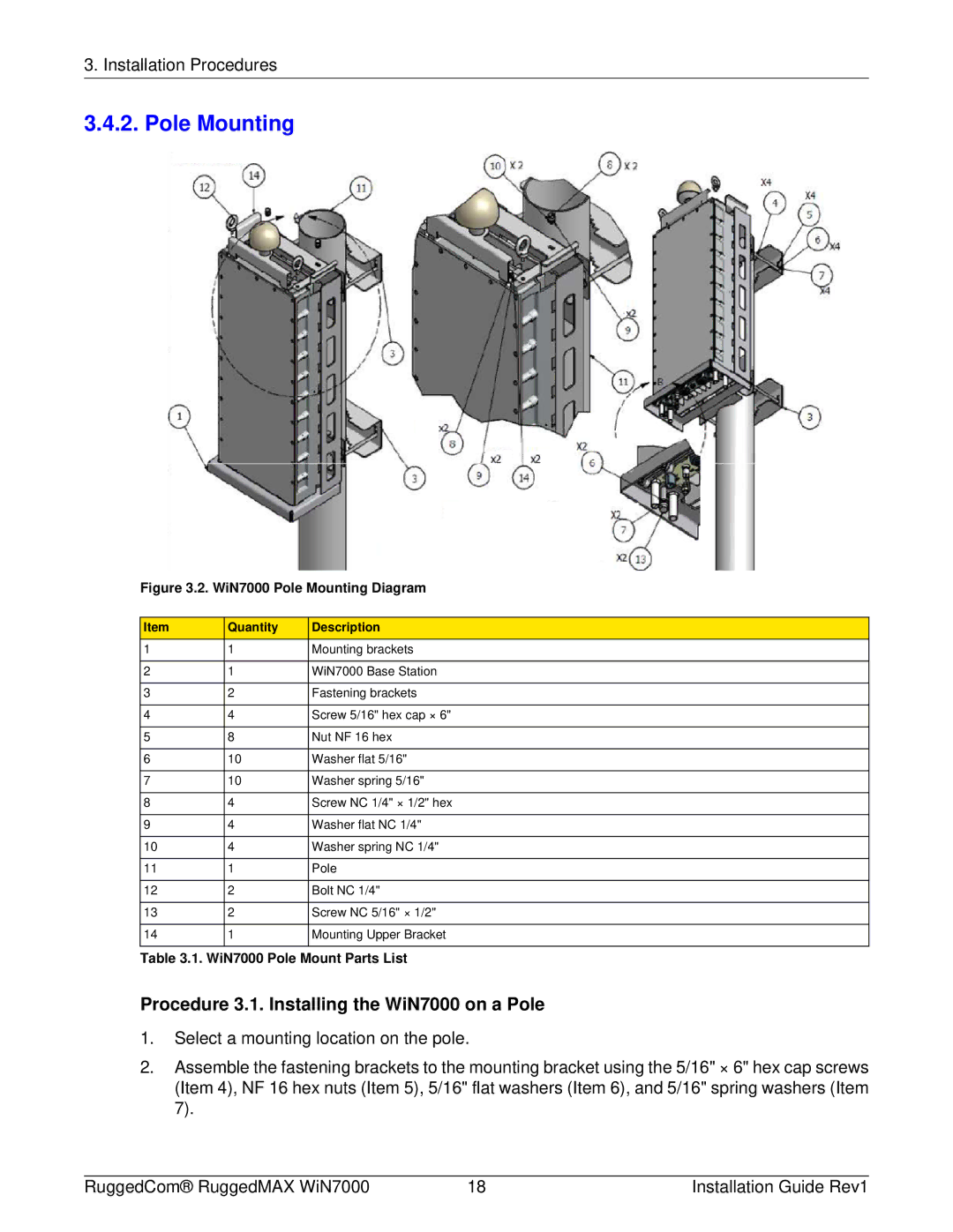
Figure 3.2. WiN7000 Pole Mounting Diagram
Item | Quantity | Description |
1 | 1 | Mounting brackets |
|
|
|
2 | 1 | WiN7000 Base Station |
|
|
|
3 | 2 | Fastening brackets |
|
|
|
4 | 4 | Screw 5/16" hex cap × 6" |
|
|
|
5 | 8 | Nut NF 16 hex |
|
|
|
6 | 10 | Washer flat 5/16" |
|
|
|
7 | 10 | Washer spring 5/16" |
|
|
|
8 | 4 | Screw NC 1/4" × 1/2" hex |
|
|
|
9 | 4 | Washer flat NC 1/4" |
|
|
|
10 | 4 | Washer spring NC 1/4" |
|
|
|
11 | 1 | Pole |
|
|
|
12 | 2 | Bolt NC 1/4" |
|
|
|
13 | 2 | Screw NC 5/16" × 1/2" |
|
|
|
14 | 1 | Mounting Upper Bracket |
|
|
|
Table 3.1. WiN7000 Pole Mount Parts List
Procedure 3.1. Installing the WiN7000 on a Pole
1.Select a mounting location on the pole.
2.Assemble the fastening brackets to the mounting bracket using the 5/16" × 6" hex cap screws (Item 4), NF 16 hex nuts (Item 5), 5/16" flat washers (Item 6), and 5/16" spring washers (Item 7).
RuggedCom® RuggedMAX WiN7000 | 18 | Installation Guide Rev1 |
