INSTALLATION

UNIT INSTALLATION

HORIZONTAL TERMINATION WITH FLEX VENT SYSTEM

1)Locate the unit in the framing, rough in the gas (preferably on the right side of the unit) and the electrical (Junction block is on the left side) on the left. Locate the centerline of the termination and mark wall accordingly. Cut an 11"(279mm) hole in the wall (inside dimension).

Note: A top clearance of 2-1/2"(64mm) and side & bottom clearance of 1-1/2"(38mm) must be maintained exceptthatonlya1"(25mm)clearance is needed at the termination end. We recommend framing a 11"(279mm) x 11"(279mm)(insidedimensions)hole togivestructuralrigidityformounting the termination.

Note: If installing termination on a siding covered wall, a vinyl siding standoff or vinyl furring strips must be used to ensure that the termination is not recessed into the siding.

2)Level the fi replace and fasten it to the fram- ing using nails or screws through the nailing strips.

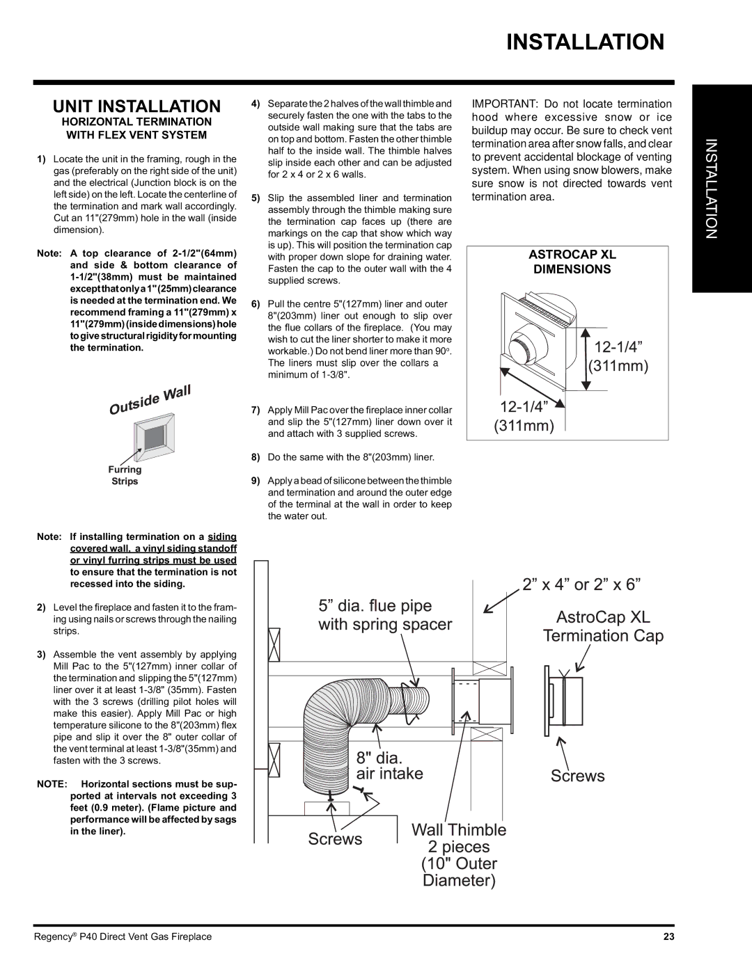
3)Assemble the vent assembly by applying Mill Pac to the 5"(127mm) inner collar of the termination and slipping the 5"(127mm) liner over it at least 1-3/8" (35mm). Fasten with the 3 screws (drilling pilot holes will make this easier). Apply Mill Pac or high temperature silicone to the 8"(203mm) fl ex pipe and slip it over the 8" outer collar of the vent terminal at least 1-3/8"(35mm) and fasten with the 3 screws.

NOTE: Horizontal sections must be sup- ported at intervals not exceeding 3 feet (0.9 meter). (Flame picture and performance will be affected by sags in the liner).

4)Separate the 2 halves of the wall thimble and securely fasten the one with the tabs to the outside wall making sure that the tabs are on top and bottom. Fasten the other thimble half to the inside wall. The thimble halves slip inside each other and can be adjusted for 2 x 4 or 2 x 6 walls.

5)Slip the assembled liner and termination assembly through the thimble making sure the termination cap faces up (there are markings on the cap that show which way is up). This will position the termination cap with proper down slope for draining water. Fasten the cap to the outer wall with the 4 supplied screws.

6)Pull the centre 5"(127mm) liner and outer 8"(203mm) liner out enough to slip over the fl ue collars of the fi replace. (You may wish to cut the liner shorter to make it more workable.) Do not bend liner more than 90o.

The liners must slip over the collars a minimum of 1-3/8".

7)Apply Mill Pac over the fi replace inner collar and slip the 5"(127mm) liner down over it and attach with 3 supplied screws.

8)Do the same with the 8"(203mm) liner.

9)Apply a bead of silicone between the thimble and termination and around the outer edge of the terminal at the wall in order to keep the water out.

IMPORTANT: Do not locate termination hood where excessive snow or ice buildup may occur. Be sure to check vent termination area after snow falls, and clear to prevent accidental blockage of venting system. When using snow blowers, make sure snow is not directed towards vent termination area.

ASTROCAP XL

DIMENSIONS

INSTALLATION

Regency® P40 Direct Vent Gas Fireplace

23

Page 23
Image 23
Regency P40-NG, P40-LP installation manual Unit Installation, Astrocap XL Dimensions

P40, P40-LP, P40-NG specifications

The Regency P40 series, comprising the P40-LP, P40, and P40-NG models, represents a significant advancement in the world of portable radio communications. Designed with both versatility and performance in mind, these devices cater to a diverse range of users, from public safety professionals to outdoor enthusiasts.

One of the standout features of the P40 series is its robust build quality. The radios are engineered to withstand harsh environments, boasting IP67 water and dust resistance ratings. This ensures reliable performance even in challenging conditions, making them ideal for emergency responders who operate in adverse weather or rugged terrains. The P40's durable design is complemented by a lightweight construction, allowing for prolonged use without fatigue.

The P40 series is equipped with advanced digital technology that enhances both audio clarity and range. With a powerful speaker and noise-canceling capabilities, users can communicate clearly even in noisy surroundings. The P40-NG model takes this a step further by incorporating digital signal processing (DSP) technology, which optimizes sound for both transmission and reception.

Battery life is a critical aspect of any portable device, and the P40 series excels in this regard. With options for high-capacity lithium-ion batteries, users can expect extended operational times, vital for those on long shifts or field operations. Additionally, the smart battery management system provides real-time battery status updates, ensuring users are never caught off guard.

Interoperability is another key characteristic of the P40 series. The radios support multiple frequency bands and can seamlessly integrate with existing communication infrastructures. This capability is particularly beneficial for agencies that require coordination across various channels and networks.

User-friendly interfaces define the P40 series, with intuitive controls and customizable features. The color display on the P40 and P40-NG models enhances usability, allowing for easy navigation through settings and features. Furthermore, programmable buttons facilitate quick access to frequently used functions, ensuring efficient communication even in high-pressure scenarios.

Overall, the Regency P40-LP, P40, and P40-NG radios embody reliability, advanced technology, and ruggedness, making them essential tools for effective communication in a variety of demanding environments. With their combination of durability, audio performance, and battery life, these radios stand out as a top choice for both professional and recreational use.