INSTALLATION

INSTALLATION

UNIT ASSEMBLY

PRIOR TO

INSTALLATION

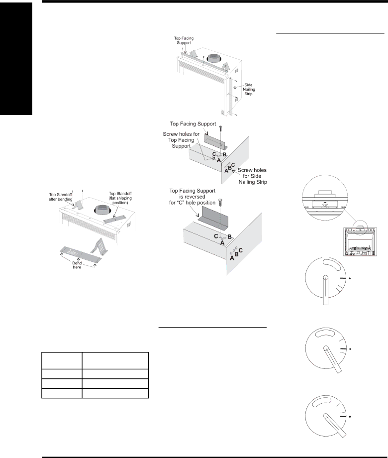
NOTE:TheTopFacingSupport,theSideNailing Strips and the 2 Top Standoffs must be correctly positioned and attached before unit is slipped into position.

TOP STANDOFF ASSEMBLY

The top standoffs are shipped in a fl at position and must be folded into shape and attached.

1)Remove the standoffs from top of the fi replace.

2)Take each standoff and bend into the correct shape. Bend up at the bend lines until the screw holes in the standoff and the pre- punched screw holes on the fi replace top line up.

3)Attach the standoff securely to the top with 2 screws per standoff (on opposite corners).

TOP FACING SUPPORT AND

SIDE NAILING STRIPS

Determine the total thickness of facing material to allow the fi nished surface to be fl ush with the front of the unit. Total facing thickness can vary from 1/2" (13mm) to 1-1/4" (32mm) thick.

TheTopFacingSupport&SideNailingStripscan be mounted in 3 different positions depending on the thickness of the facing material.

Screw

Facing Material Depth

Position


A1/2" / 13mm

B7/8" / 22mm

C*

1-1/4" / 32mm

*For "C" screw position the top facing support is reversed.

1)Mount Top Facing Support using the 3 supplied screws into the three pre-punched screw holes on the top front of the unit. Use hole positions A, B, or C depending on your facing depth.

Note: For screw position C with a facing material depth of 1-1/4" (32mm), the top facing support must be reversed.

2)Use the same screw hole position for the Side Nailing Strips as was used for the Top Facing Support. Attach each side nailing strip using 3 screws.

Note: When installing side strips into position C, the side strips are not reserved.

VENTING

INTRODUCTION

The P40 uses the "balanced fl ue" technology Co Axial system. The inner liner vents products of combustion to the outside while the outer liner draws outside combustion air into the combustion chamber thereby eliminating the need to use heated room air for combustion and losing warm room air up the chimney.

Note: These flue pipes must not be connected to any other appliance.

The gas appliance and vent system must be vented directly to the outside of the building, and never be attached to a chimney serving a separate solid fuel or gas burning appliance.

Each direct vent gas appliance must use it's own separate vent system. Common vent systems are prohibited.

VENT RESTRICTOR

POSITION

Vent restriction is required for certain venting installations, see the diagrams in the "Venting Arrangements" section to determine if they are required for your installation.

To set the Vent restriction as indicated in the diagrams in the "VentingArrangements" section, refer to the instructions below;

1)Remove the top louver if installed.

2)Loosen the screw on the vent restrictor indicating plate.

3)Rotate the vent restrictor adjustment rod counter clockwise to line up the slot on the indicating plate with the point on the air box to the required setting.

4)Tighten screw to lock position.

Screw

Point on AirBox

Factory Set Vent Restrictor Setting

(no adjustment required)

Point on AirBox

Vent Restrictor setting at Set 1

Point on AirBox

Vent Restrictor setting at Set 2

12

Regency® P40 Direct Vent Gas Fireplace

Page 12
Image 12
Regency P40-NG, P40-LP Unit Assembly Prior to Installation, Venting Introduction, Vent Restrictor Position, Screw

P40, P40-LP, P40-NG specifications

The Regency P40 series, comprising the P40-LP, P40, and P40-NG models, represents a significant advancement in the world of portable radio communications. Designed with both versatility and performance in mind, these devices cater to a diverse range of users, from public safety professionals to outdoor enthusiasts.

One of the standout features of the P40 series is its robust build quality. The radios are engineered to withstand harsh environments, boasting IP67 water and dust resistance ratings. This ensures reliable performance even in challenging conditions, making them ideal for emergency responders who operate in adverse weather or rugged terrains. The P40's durable design is complemented by a lightweight construction, allowing for prolonged use without fatigue.

The P40 series is equipped with advanced digital technology that enhances both audio clarity and range. With a powerful speaker and noise-canceling capabilities, users can communicate clearly even in noisy surroundings. The P40-NG model takes this a step further by incorporating digital signal processing (DSP) technology, which optimizes sound for both transmission and reception.

Battery life is a critical aspect of any portable device, and the P40 series excels in this regard. With options for high-capacity lithium-ion batteries, users can expect extended operational times, vital for those on long shifts or field operations. Additionally, the smart battery management system provides real-time battery status updates, ensuring users are never caught off guard.

Interoperability is another key characteristic of the P40 series. The radios support multiple frequency bands and can seamlessly integrate with existing communication infrastructures. This capability is particularly beneficial for agencies that require coordination across various channels and networks.

User-friendly interfaces define the P40 series, with intuitive controls and customizable features. The color display on the P40 and P40-NG models enhances usability, allowing for easy navigation through settings and features. Furthermore, programmable buttons facilitate quick access to frequently used functions, ensuring efficient communication even in high-pressure scenarios.

Overall, the Regency P40-LP, P40, and P40-NG radios embody reliability, advanced technology, and ruggedness, making them essential tools for effective communication in a variety of demanding environments. With their combination of durability, audio performance, and battery life, these radios stand out as a top choice for both professional and recreational use.