MAINTENANCE
15)Disconnect the compression fi tting at the solenoid valve.
16)Remove the solenoid valve from the main valve.
Solenoid Valve
Compression Fittings
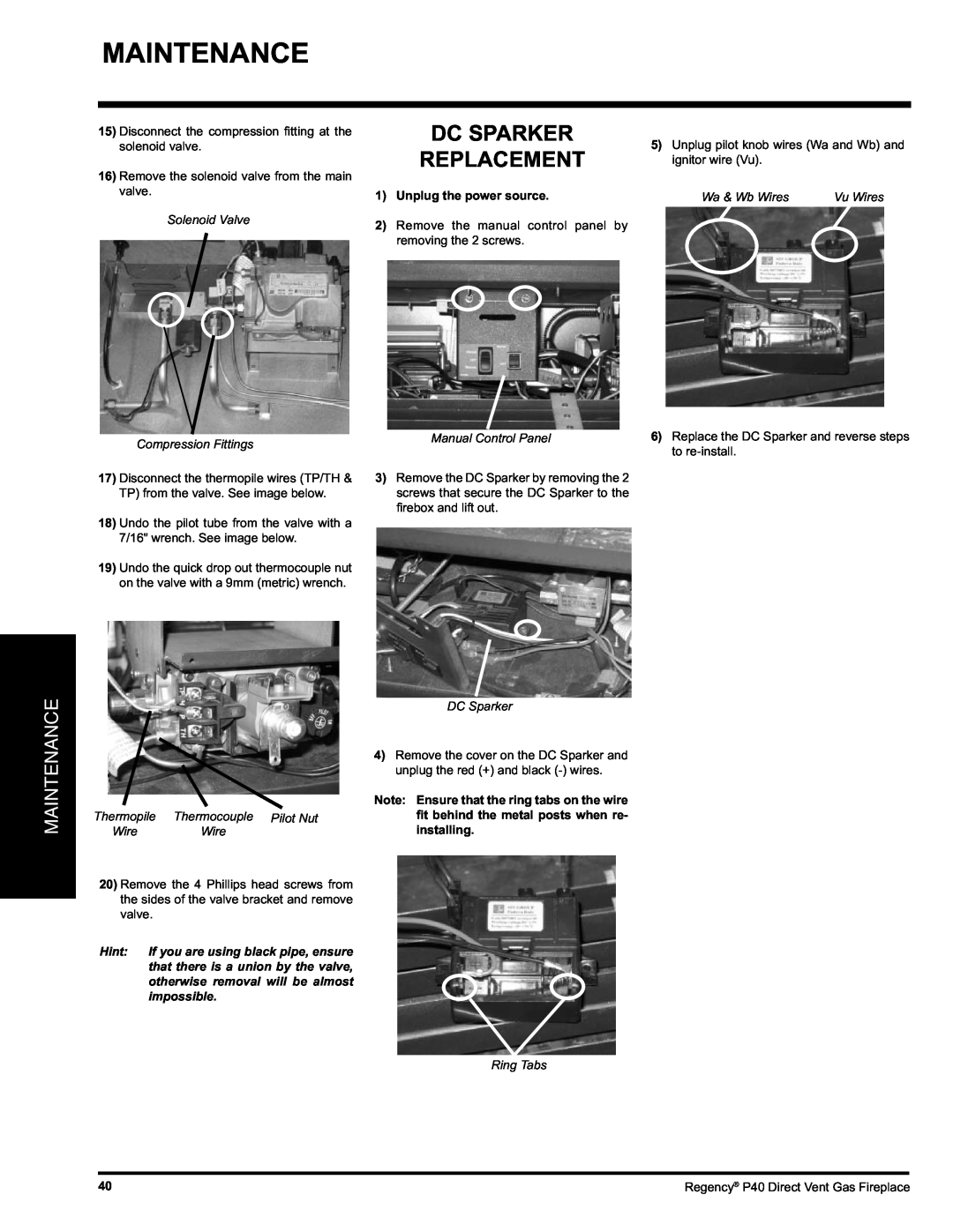
17)Disconnect the thermopile wires (TP/TH & TP) from the valve. See image below.
18)Undo the pilot tube from the valve with a 7/16" wrench. See image below.
19)Undo the quick drop out thermocouple nut on the valve with a 9mm (metric) wrench.
DC SPARKER
REPLACEMENT
1)Unplug the power source.
2)Remove the manual control panel by removing the 2 screws.
Manual Control Panel
3)Remove the DC Sparker by removing the 2 screws that secure the DC Sparker to the fi rebox and lift out.
5)Unplug pilot knob wires (Wa and Wb) and ignitor wire (Vu).
Wa & Wb Wires | Vu Wires |
6)Replace the DC Sparker and reverse steps to
MAINTENANCE
|
| DC Sparker |
|
| 4) Remove the cover on the DC Sparker and |
|
| unplug the red (+) and black |
|
| Note: Ensure that the ring tabs on the wire |
Thermopile | Thermocouple Pilot Nut | fit behind the metal posts when re- |
Wire | Wire | installing. |
20)Remove the 4 Phillips head screws from the sides of the valve bracket and remove valve.
Hint: If you are using black pipe, ensure that there is a union by the valve, otherwise removal will be almost impossible.
Ring Tabs
40 | Regency® P40 Direct Vent Gas Fireplace |