3. Installation Procedures
Procedure 3.2. Installing the WiN7000 on a Wall
1.Select a mounting location.
2.Place the mounting bracket on the wall and mark the location of the four mounting holes, two at the top and two at the bottom.
3.With a 5/16" drill bit suitable for the wall material, drill holes at the marked locations.
4.Insert the 5/16" dowels (Item 10) into the holes.
5.Assemble four 5/16" flat washers (Item 8), four 5/16" spring washers (Item 9), and four 5/16" × 2" hex cap screws (Item 7) into the holes on the mounting bracket.
6.Secure the mounting bracket to the wall.
7.Lift the base station by the eye bolts and secure it to the mounting bracket. At the top of the unit and mounting bracket, use NC 1/4" × 1/2" hex screws (Item 3), NC 14" flat washers (Item 4), and NC 1/4" spring washers (Item 5).
8.Complete the wiring connections.
Seal all connectors with
3.4.4. Tower Mount
Follow the same procedure as for wall mounting; see Section 3.4.3, “Wall Mounting”. Ensure that the tower can hold the load of the base station.
3.4.5. Cable Connections
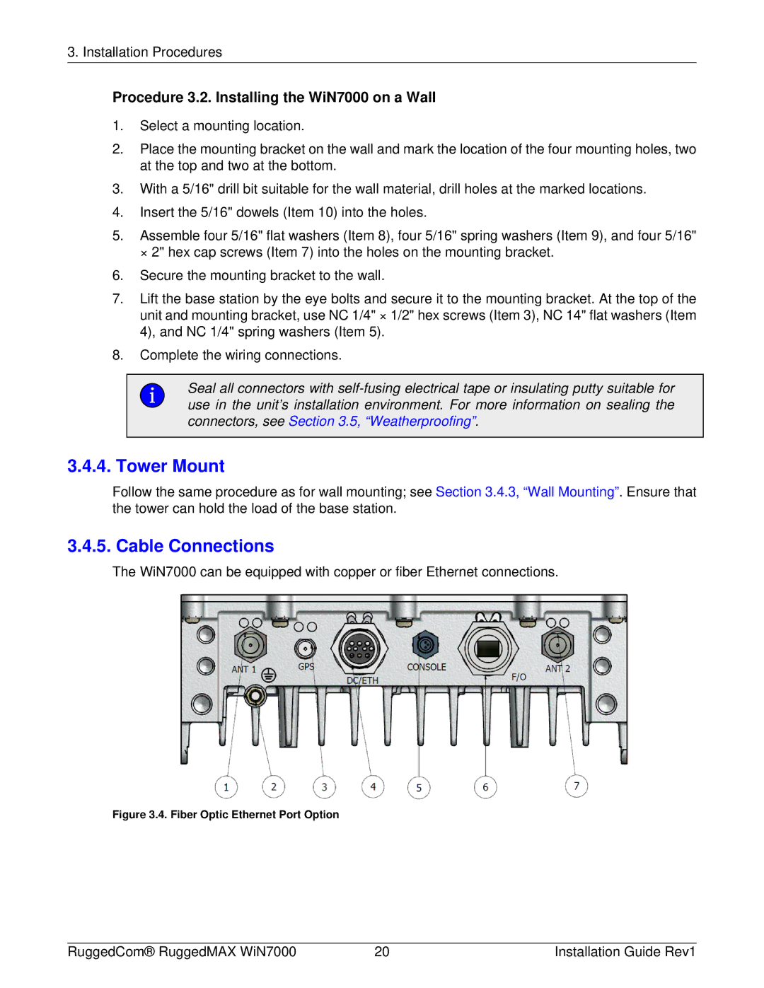
The WiN7000 can be equipped with copper or fiber Ethernet connections.
Figure 3.4. Fiber Optic Ethernet Port Option
RuggedCom® RuggedMAX WiN7000 | 20 | Installation Guide Rev1 |