3.Installation Procedures
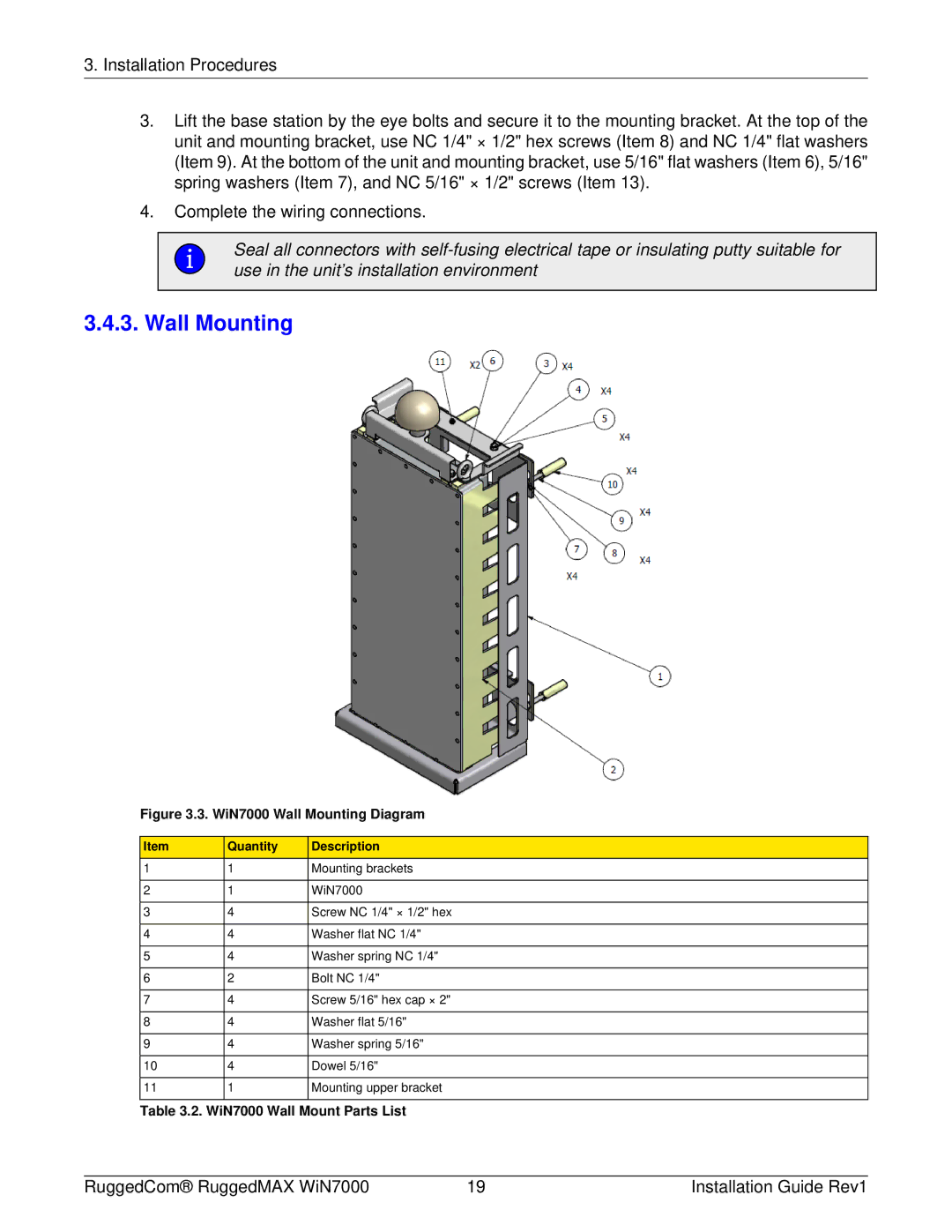
3.Lift the base station by the eye bolts and secure it to the mounting bracket. At the top of the unit and mounting bracket, use NC 1/4" × 1/2" hex screws (Item 8) and NC 1/4" flat washers (Item 9). At the bottom of the unit and mounting bracket, use 5/16" flat washers (Item 6), 5/16" spring washers (Item 7), and NC 5/16" × 1/2" screws (Item 13).
4.Complete the wiring connections.
Seal all connectors with
3.4.3. Wall Mounting
Figure 3.3. WiN7000 Wall Mounting Diagram
Item | Quantity | Description |
1 | 1 | Mounting brackets |
|
|
|
2 | 1 | WiN7000 |
|
|
|
3 | 4 | Screw NC 1/4" × 1/2" hex |
|
|
|
4 | 4 | Washer flat NC 1/4" |
|
|
|
5 | 4 | Washer spring NC 1/4" |
|
|
|
6 | 2 | Bolt NC 1/4" |
|
|
|
7 | 4 | Screw 5/16" hex cap × 2" |
|
|
|
8 | 4 | Washer flat 5/16" |
|
|
|
9 | 4 | Washer spring 5/16" |
|
|
|
10 | 4 | Dowel 5/16" |
|
|
|
11 | 1 | Mounting upper bracket |
|
|
|
Table 3.2. WiN7000 Wall Mount Parts List
RuggedCom® RuggedMAX WiN7000 | 19 | Installation Guide Rev1 |