Thermal Expansion

Determine if a check valve exists in the inlet water line. Check with your local water utility company. It may have been installed in the cold water line as a separate back flow preventer, or it may be part of a pressure reducing valve, water meter or water softener. A check valve located in the cold water inlet line can cause what is referred to as a “closed water system”. A cold water inlet line with no check valve or back flow prevention device is referred to as an “open” water system.

As water is heated, it expands in volume and creates an increase in the pressure within the water system. This action is referred to as “thermal expansion”. In an “open” water system, expanding water which exceeds the capacity of the water heater flows back into the city main where the pressure is easily dissipated.

A “closed water system”, however, prevents the expanding water from flowing back into the main supply line, and the result of “thermal expansion” can create a rapid and dangerous pressure increase in the water heater and system piping. This rapid pressure increase can quickly reach the safety setting of the relief valve, causing it to operate during each heating cycle. Thermal expansion, and the resulting rapid, and repeated expansion and contraction of components in the water heater and piping system can cause premature failure of the relief valve, and possibly the heater itself. Replacing the relief valve will not correct the problem!

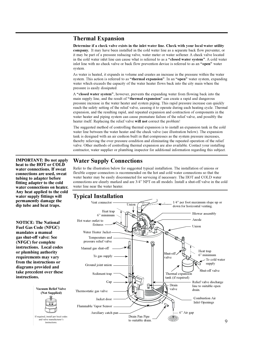
The suggested method of controlling thermal expansion is to install an expansion tank in the cold water line between the water heater and the check valve (see illustration below). The expansion tank is designed with an air cushion built in that compresses as the system pressure increases, thereby relieving the over pressure condition and eliminating the repeated operation of the relief valve. Other methods of controlling thermal expansion are also available. Contact your installing contractor, water supplier or plumbing inspector for additional information regarding this subject.

IMPORTANT: Do not apply heat to the HOT or COLD water connections. If sweat connections are used, sweat tubing to adapter before fitting adapter to the cold water connections on heater. Any heat applied to the cold water supply fittings will permanently damage the dip tube and heat traps.

NOTICE: The National Fuel Gas Code (NFGC) mandates a manual gas shut-off valve: See (NFGC) for complete instructions. Local codes or plumbing authority requirements may vary from the instructions or diagrams provided and take precedent over these instructions.

Vacuum Relief Valve

(Not Supplied)

If required, install per local codes

and valve manufacturer’s

instructions.

Water Supply Connections

Refer to the illustration below for suggested typical installation. The installation of unions or flexible copper connectors is recommended on the hot and cold water connections so that the water heater may be easily disconnected for servicing if necessary. The HOT and COLD water connections are clearly marked and are 3/4” NPT on all models. Install a shut-off valve in the cold water line near the water heater.

Typical Installation


Vent connector


1/4” per foot maximum slope up or


Union


down for horizontal venting.


Heat trap


Blower assembly


6” minimum


Anode


Hot water outlet to


fixtures


Union


Water Heater Jacket


Temperature and


pressure relief valve


Manual gas shut-off


Shut-off

Heat trap


To gas supply


6” minimum


valve


To cold water


Ground joint union


supply


Sediment trap


Thermal expansion

Shut-off valve


Cap


tank (if required)


Relief valve discharge


Drain


line to suitable open


Thermostatic gas valve


valve

drain.


Combustion Air


Jacket door


Flammable Vapor Sensor


Inlet Openings


6” Air gap


Auxiliary catch pan


Drain Pan Pipe


9


to suitable drain.


Page 9
Image 9
Ruud AP14236 installation instructions Thermal Expansion, Water Supply Connections, Typical Installation

AP14236 specifications

Ruud AP14236 is a highly efficient air conditioning unit that stands out in the residential HVAC market for its remarkable performance and innovative technology. This model is specifically engineered to provide optimal cooling and heating solutions, offering homeowners comfort year-round while also emphasizing energy efficiency.

One of the key features of the Ruud AP14236 is its efficiency rating, showcased by its SEER (Seasonal Energy Efficiency Ratio) rating, which provides users with an indication of energy consumption versus cooling output. With ratings often exceeding 14, the unit is designed to reduce energy bills significantly while maintaining a comfortable indoor environment. In addition to SEER, the unit boasts an HSPF (Heating Season Performance Factor) that guarantees excellent performance during colder months.

The Ruud AP14236 utilizes advanced inverter technology that allows for variable speed operation. This technology enables the air conditioner to adjust its cooling output based on the actual temperature in the home, leading to lower energy consumption while ensuring that the desired climate is reached swiftly and efficiently. This feature not only enhances comfort but also prolongs the lifespan of the unit, as it does not require the constant on-off cycling seen in traditional systems.

Equipped with an enhanced filtration system, the Ruud AP14236 significantly improves indoor air quality by capturing dust, allergens, and other particulates. This characteristic is particularly advantageous for those with allergies or respiratory conditions, as it creates a healthier living environment.

Durability is another hallmark of the Ruud AP14236, featuring robust construction materials designed to withstand the rigors of varied weather conditions. The unit's cabinet is often galvanized and treated to resist rust, ensuring longevity and reducing maintenance issues.

Noise reduction is also a primary focus in the design of Ruud AP14236. The unit operates quietly, allowing for comfortable living spaces without the disruptive sounds commonly associated with air conditioning systems. This is achieved through sound-dampening technology and acoustic insulation.

In summary, the Ruud AP14236 is engineered for energy efficiency, versatility, durability, and quiet operation. Homeowners seeking a reliable and efficient air conditioning solution will find that this unit meets their needs while providing year-round comfort and improved air quality.