ASSEMBLY
UNPACKING
This product requires assembly.
nCarefully lift the saw from the carton by the carrying handle and the saw base, and place it on a level work surface.
NOTE: This tool is heavy. To avoid back injury, lift with your legs, not your back, and get help when needed.
nThis saw has been shipped with the saw arm secured in the down position. To release the saw arm, push down on the top of the saw arm, cut the
nLift the saw arm by the handle. Hand pressure should remain on the saw arm to prevent sudden rise upon release of the tie wrap.
nInspect the tool carefully to make sure no breakage or damage occurred during shipping.
nDo not discard the packing material until you have care- fully inspected and satisfactorily operated the tool.
nThe saw is factory set for accurate cutting. After assembling it, check for accuracy. If shipping has influenced the settings, refer to specific procedures explained in this manual.
nIf any parts are damaged or missing, please call
WARNING:
If any parts are missing, do not operate this tool until the missing parts are replaced. Failure to do so could result in possible serious personal injury.
WARNING:
Do not attempt to modify this tool or create accesso- ries not recommended for use with this tool. Any such alteration or modification is misuse and could result in a hazardous condition leading to possible serious personal injury.
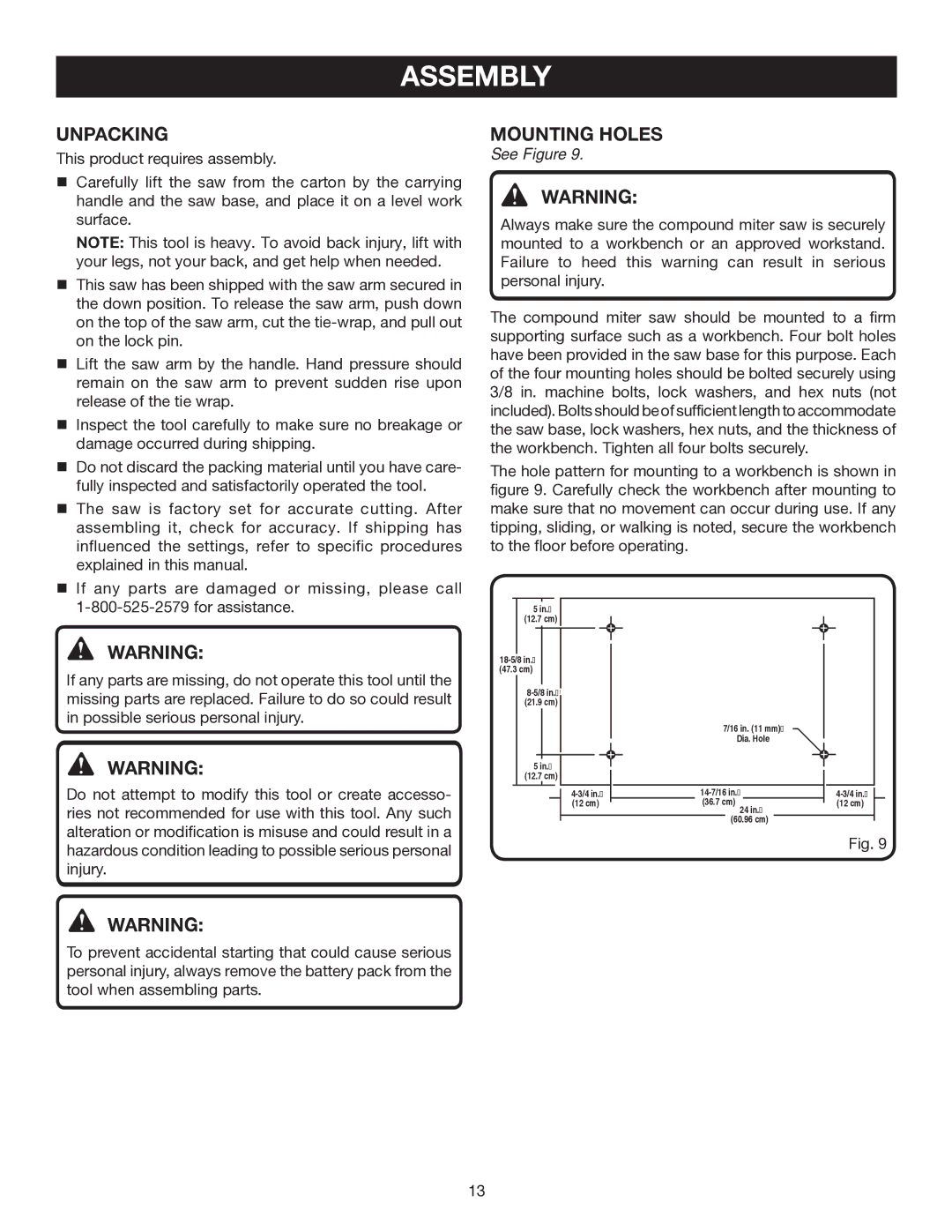
MOUNTING HOLES
See Figure 9.
WARNING:
Always make sure the compound miter saw is securely mounted to a workbench or an approved workstand. Failure to heed this warning can result in serious personal injury.
The compound miter saw should be mounted to a firm supporting surface such as a workbench. Four bolt holes have been provided in the saw base for this purpose. Each of the four mounting holes should be bolted securely using 3/8 in. machine bolts, lock washers, and hex nuts (not included). Bolts should be of sufficient length to accommodate the saw base, lock washers, hex nuts, and the thickness of the workbench. Tighten all four bolts securely.
The hole pattern for mounting to a workbench is shown in figure 9. Carefully check the workbench after mounting to make sure that no movement can occur during use. If any tipping, sliding, or walking is noted, secure the workbench to the floor before operating.
5 in.�
(12.7 cm)
(47.3 cm)
![]()
![]()
| 7/167/16”in. DIA(11 | .mm)HOLE� |
| Dia. Hole | |
5 in.� |
|
|
(12.7 cm) |
|
|
(36.7 cm) 24 in.� |
| |
(12 cm) | (12 cm) | |
| (60.96 cm) | |
Fig. 9
WARNING:
To prevent accidental starting that could cause serious personal injury, always remove the battery pack from the tool when assembling parts.
13
