AlphaPC 164UX/BX Motherboard Windows NT User’s Manual
AlphaPC 164UX/BX Motherboard Windows NT User’s Manual
Contents
Configuring for Windows NT
Memory and Microprocessor Configuration
Interrupts and ISA Bus Addresses
Battery Recycle/Disposal Information Supporting Products
Troubleshooting
Support,Products and Documentation
Figures
Tables
Difference between AlphaPC 164UX and 164BX
About This Manual
Manual Conventions and Terminology
Manual Conventions and Terminology
This term Refers to
Features of the AlphaPC164UX Motherboard
AlphaPC 164UX Features
AlphaPC 164UX Jumper/Connector Location
AlphaPC 164UX Jumper/Connector List
Power Requirements
Power Requirements
Power Supply DC Current Requirements
Environmental Requirements
Physical Parameters
Physical Parameters
Board Measurements and Hole Locations
Board measurement and Hole Position Diagram
3shows the Board Vertical Clearance for the AlphaPC 164UX
Board Vertical Clearance Diagram
ATX Back Panel Dimension
Physical Parameters ATX Cutout Information
AlphaPC 164UX Jumper Configuration
AlphaPC 164UX Configuration Jumpers
CPU Speed Selection Option 1,2,3, &4
Boot Option Jumper Option
Bcache Size Jumpers Option 14,15
AlphaPC 164UX Connector Pinouts
PCI Bus Connector Pinouts
1shows the PCI bus connector pinouts
PCI Bus Connector Pinouts
PCI Bus Connector Pinouts
REQ#
ISA Expansion Bus Connector Pinouts
ISA Expansion Bus Connector Pinouts
2shows the ISA expansion bus connector pinouts
ISA Expansion Bus Connector Pinouts J10
Sdram Dimm Connector Pinouts
Sdram Dimm Connector Pinouts
3shows the Sdram Dimm connector pinouts
Sdram Dimm Connector Pinouts U3 through U8
Eide Drive Bus Connector Pinouts
Eide Drive Bus Connector Pinouts
4shows the Eide drive bus connector pinouts
Eide Drive Bus Connector Pinouts J24
Diskette Drive Bus Connector Pinouts
Parallel Bus Connector Pinouts
Diskette Drive Bus Connector Pinouts
5shows the diskette floppy drive bus connector pinouts
COM1/COM2 Serial Line Connector Pinouts
Keyboard/Mouse Connector Pinouts
COM1/COM2 Serial Line Connector Pinouts
7shows the COM1/COM2 serial line connector pinouts
Input Power Connector Pinouts
Narrow Scsi Bus Connector UX only
Input Power Connector Pinouts
9shows the input power connector pinouts
Fast and Wide Scsi Bus Connector UX only
12 10/100 Mbit Ethernet Connector Pinouts UX only
Fast and Wide Scsi Bus Connector UX only
11shows the Fast and Wide Scsi bus connector pinouts
Speaker Connector Pinouts
Microprocessor Fan Power Connector Pinouts
Pin Power LED Connector Pinouts
Speaker Connector Pinouts
IDE Drive LED Connector Pinouts
Reset Switch Connector Pinouts
Soft Power Switch Connector Pinouts
Scsi LED Connector Pinouts
Configuring Sdram Memory
Memory and Microprocessor Configuration
AlphaPC 164UX Sdram Memory Configurations
Configuring Sdram Memory
Upgrading Sdram Memory
Upgrading Sdram Memory
Preparatory Information
Increasing Microprocessor Speed
Required Tools
Installing the 21164 Microprocessor
Removing the 21164 Microprocessor
Shows the Fan/Heat-Sink Assembly on AlphaPC 164UX
Increasing Microprocessor Speed
Interrupts and ISA Bus Addresses
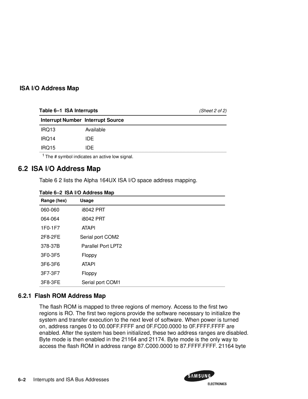
Interrupts
1lists each Alpha 164UX ISA interrupt and its source
ISA Interrupts
ISA I/O Address Map
ISA I/O Address Map
Flash ROM Address Map
Lists the Alpha 164UX ISA I/O space address mapping
ISA I/O Address Map
Configuring for Windows NT
Navigating the Arcsbios
Exploring the Arcsbios
Navigation Keys
Arcsbios
Arcsbios Setup
Arcsbios Setup
Run a Program
Environment Variables
Advanced Setup
Resources
System Configuration
System Time and Date
Upgrading the Arcsbios Firmware
Installing Windows NT
Upgrading the Arcsbios Firmware Print Configuration
Add-in Board Utilities
Installing Windows NT Before Installing Windows NT
Type in CD\alpha\arcinst.exe
Windows NT Setup
Installing Windows NT
If you want to accept, press Enter
Installing Windows NT
10Configuring for Windows NT
Enter
Network and select wired to a network. Click the Next Button
Installing Windows NT
14Configuring for Windows NT
Troubleshooting
Troubleshooting steps No Video
Troubleshooting steps Keyboard error on boot up
Hardware Startup
Beep Codes
Post Codes
Replace the keyboard
Beep Codes
Safe Arcsbios
Post Codes
Starting the Safe Arcsbios
Battery Recycle/Disposal Information
Battery Recycle/Disposal Information
Supporting Products
Memory
VisionTek Lakeside Dr Gurnee,IL Phone Fax
Table A-1 Samsung Dimm Part Number List
Memory
Viking Components Columbia Laguna Hills,Ca Phone Fax
Table A-2 VisionTek Dimm Part Number List
Table A-3 Viking Components Dimm Part Number List
Power Supply
Thermal Products
Thermal Products
Table A-5 Dense-Pac Microsystems Dimm Part Number List
Enclosure
Enclosure
Support,Products and Documentation
Samsung Alpha Products
Following table lists some of the available documentation
Samsung Alpha Documentation
4Support,Products and Documentation

