Samsung Electronics
Functional parts and safety devices
Indoor unit PCB
Noise level
Electronic expansion valve kit
IOverview
What is DVM?
DVM system series
Features of DVM
Customized air conditioner
Comparison of DVM with conventional air conditioners
DVM air conditioner
Variable compressor
Principle of the digital compressor
Refrigerant flow rates control
PWM Pulse Width Modulation valve
Easy installation
Long & single piping system
Convenient centralized control
Minimizing operation costs
Space Saving
Conventional System DVM System
DVM vs VAV
Excellent energy efficiency
Zone Test
DVM test condition
VAV test condition
Zone control conditions
Zone control Sample #1 Sample #2 Sample #3 Sample #4
DVM line-up
Numbering system of model
Indoor unit and outdoor unit Conventional model Model
Indoor unit and outdoor unit New Model
Model
Indoor unit
④ Power supply
② Mode
⑥ Combination of indoor unit
③ Capacity HP x 10, 3 digits
Options
Parts Model Standard for model name Example
MCM- ① ② ③ ④
MSC- ① ② ③ ④ ⑤
Design Power supply Model CapacityHP Refrigerant Main
Combination
Outdoor unit
Cooling only
Design Max. connectible
Super Remark Main
Indoor units
Cooler
Heat pump
~20.8 ~18.8 11.0~29.0 14.0~36.4 14.0~28.0
Design Power 0kW 6kW 2kW 5kW
System line-up
Indoor unit
Design Power 0kW 2kW 3kW
IIControl System
Remote controller
Wireless remote controller
Timer Cancel button
On/Off & Timer set/cancel button Heat pump Operating mode
Duct type
Wired remote controller
On/Off timer button
Selection button
Cooling only Operating mode
Temperature
Operating mode Selection button Heat pump
Operating mode Selection button
Operating mode Temperature adjustment On/Off button Buttons
Test button Filter reset button Mode selection button
Centralized controller
Function controller
Receiver & display unit Duct type
Concealed type
Cooling only
Heat pump
Standard type
Transmitter
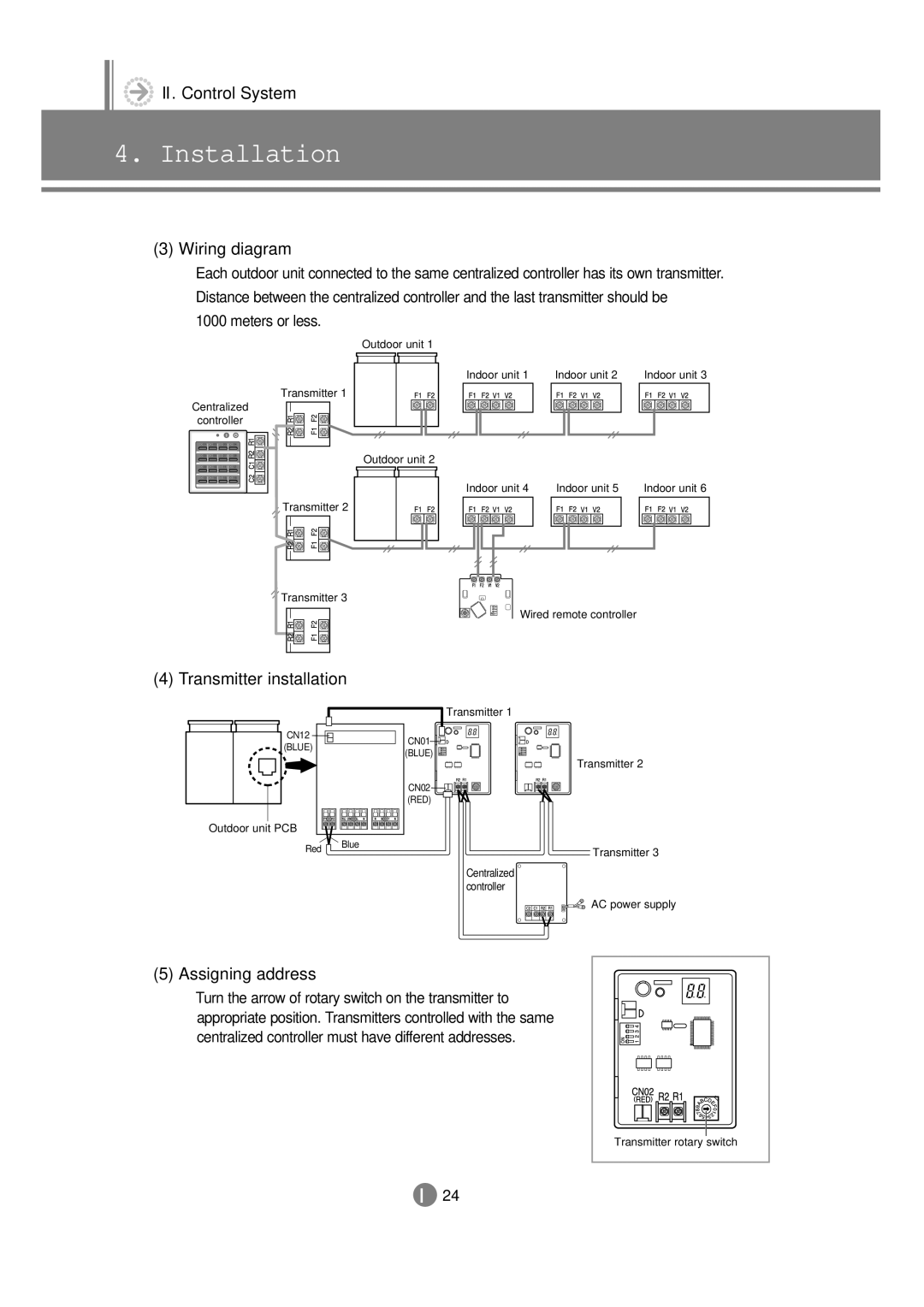
Installation
Accessories
Installation
Wired Remote Controller Cable-Tie2
Setting up option switches
Switch No
Original Position
Example of installing wired remote controller
Individual control
Wiring diagram
Transmitter installation
Assigning address
Button No
Case of Installing wired remote controller together
SW03 switch in indoor unit Transmitter
Switch Meaning
Level of centralized controller
Reassemble the function controller
Centralized Controller Adaptor
Function Controller Outdoor unit Indoor unit
Receiver & display unit Concealed type
Receiver & display unit Standard type
Transmitter
Outdoor unit Transmitter Centralized Controller Indoor unit
Assigning address
Indoor unit
Outdoor unit
Indoor unit PCB option code
PCB option code input method example 021E31142285
Operation method Applicable button
Step
Indoor unit PCB option code
2 ~7 steps, press the mode button to make the first digit
Indoor unit PCB option code
Step Error
Option code
Type Model
AVMWC026EA0 AVMWC032CA0 AVMWC035EA0 AVMWC040CA0
AVMWC070EA0
AVMWC072CA0
AVMWH026EA0 AVMWH032CA0 AVMWH035EA0 AVMWH040CA0
Net
Integrating power distribution system
Building management system
IIIIndoor unit
Features
Way cassette type
Efficient cooling & stylish design
Features of the 1-way cassette type
Bio heat exchanger & air filter
Powerful functions
Higher & broader cooling
Features of 4-way cassette type
Fan speed adjustment
Economic installation
Duct type
High external static pressure
External static pressure Fan speed
Features of Duct type
Built-in
Low silhouette High pressure Model
Features of wall-mounted type
Wall-mounted type
BIO-components
Cross fan Body Bio pure air filter
Look at how well these filters perform
Features of floor standing type
Floor standing type
On/Off Fan speed
Turbo
Button
Sensor Button
Convenient installation
Ceiling type
Bio tech for fresh air and advanced function
Features of ceiling type
Long life filter with antibacterial treatment
Specification
50Hz
60Hz
Btu/h 18000 24000 36000 10.5 Heating 19000 26000 39000 11.4
Btu/h 18000 24000 36000 10.5
Duct type Low silhouette
AVMDC052EA0 AVMDC070EA0 AVMDH052EA0 AVMDH070EA0
AVMDC052CA0 AVMDC072CA0 AVMDH052CA0 AVMDH072CA0
Duct type Built-in
AVMBH020EA0 AVMBH026EA0 AVMBH035EA0 AVMBH052EA0 AVMBH070EA0
AVMBC032CA0
AVMBH020CA0 AVMBH032CA0 AVMBH040CA0 AVMBH052CA0 AVMBH072CA0
Duct type High pressure
AVMHC105EA0 AVMHC128EA0 AVMHH105EA0 AVMHH128EA0
AVMHC105CA0 AVMHC128CA0 AVMHH105CA0 AVMHH128CA0
220 ~ 240
AVMWH020EA0 AVMWH026EA0 AVMWH035EA0 AVMWH052EA0 AVMWH070EA0
AVMWC020CA0 AVMWC032CA0 AVMWC040CA0 AVMWC052CA0 AVMWC072CA0
4mmAq Output
Btu/h 20000 24000 28000 Heating 22000 26000 30000
AVMPC060CA0
AVMFC052EA0 AVMFC070EA0 AVMFH052EA0 AVMFH070EA0
AVMFC052CA0 AVMFC072CA0 AVMFH052CA0 AVMFH072CA0
Functional parts and safety devices
Code Name
EIS
103AT 25C=10k Ω
Code
Name
AVMWC052EA0
AVMPC083CA0 AVMPH083CA0
Capacity table
Cooling
TC Total capacity Outdoor Indoor temperature ºC, WB
12.80
Outdoor temperature Indoor temperature ºC, DB
Heating
11.4
13.8
20.0 22.0 24.0 Unit Size Temperature ºC, WB 020 14.6 032 040
20.0
10.5
Unit Size 020 032 040
Unit Size 052 072 105
13.8
Dimension
Unit mm
2kW ~ 7.2kW
10.5kW
Duct type Low silhouette
0kW ~ 4.0kW
2kW ~ 7.2kW
Duct type High pressure
Wall-Mounted type
2kW ~ 7.2kW
600mm
Ceiling type
Wireless remote controller / Receiver
MR-AC01 MR-AH01
Remote control sensor Timer indicator On/off indicator
Remote control sensor Timer indicator
Fan indicator Filter sign indicator
MGKC118IE0 MGKC118IM0 MGKC118IA0 MGKC118IC0
Timer indicator On/off button
Timer indicator Remote control sensor
On/off button Fan indicator Removing frost indicator
On/off indicator Filter sign indicator
On/off button Fan indicator
Avmwc
Operating mode Temperature Selection button
Avmpc
Avmfc Avmfh
For duct type Avmd / Avmb / Avmh
MR-AC00 MR-AH00
MRK-B00concealed type MRW-10Awire kit MRK-A00standard type
MWR-AC01 Wiring hole MWR-AH01
MWR-AC00 Wiring hole MWR-AH00
Option controller
Centralized controller Function controller
Refrigerant system diagramCooling only & heat pump
Refrigerant system diagram
Main parts status
Electric circuit diagram
Cooling only Avmkc
Heat pump Avmkh
Cooling only Avmcc
Heat pump Avmch
Cooling only Avmdc / Avmbc / Avmhc
Heat pump Avmdh / Avmbh / Avmhh
Cooling only Avmwc
Heat pump Avmwh
Cooling only Avmpc
Heat pump Avmph
Cooling only Avmfc
Heat pump Avmfh
Noise level
Overall
Duct typeBuilt-in
Octave band level
Way cassette type
026/032
035/040
052
070/072
105
Duct type Low silhouette
Duct type Built-in
035/040
070/072
Duct type High pressure
128
Wall-mounted type
035/040
070/072
Floor standing type
060
082/083
Ceiling type
Velocity of air flow & temperature distribution
Heating temperature distribution
AVMKH035
Velocity of air flow
AVMCH070
35 C
29 C
AVMCH105
32 C 29 C
AVMWH035
26 C
AVMWH070
29 C 32 C 26 C
AVMFH070
Fan specifications
Duct type Low silhoutte
Fan Speed CMM
Fan speed m3/min
070/072 026/032
Fan speed m3/min External static pressure mmAq
Duct type High pressure
Air flow m3/min
Panel
Design Status
Model Language
MGKC118IE0
MGCC095IE0
MGCH095IE0
Electronic expansion valve kit
Design Status depending on the combination
MEV-14 MEV-18
Options
Mandatory items
Optional items
MR-AC01
116
IVOutdoor unit
Unit selection with cooling load
Indoor unit selection
Outdoor unit selection
Real function data
Example for unit selection with cooling load
Given condition
Indoor unit selection
Outdoor unit selection
RVMC060GAM0 RVMC060GDM0 RVMC100GAM0
186 158 310
Charge
ISO
Saso
Output Fan output Type
ZRD72KCE-TFD
CMS
CCH
HPS
SUC.S
RVMH050CBM0 RVMH060GBM0
RVMH100GAM0 RVMH100FAM0
ZRDT14MC-TFD
Coil Siginomiya
Super cooler
MUF7201F1 SUB
Cooling
16.0
TC Total capacity, PI Power input
Outdoor Indoor temperature ºC, WB
28.0
TC Total capacity, PI Power input
Combination Indoor temperature ºC, DB
Indoor temperature ºC, DB Outdoor temperature
100
16.2
TC Total capacity, PI Power input
16.0
TC Total capacity, PI Power input
20.8
TC Total capacity, PI Power input
28.0
TC Total capacity, PI Power input
100 10.6 10.4
060
Indoor temperature ºC, DB Outdoor temperature
Upward 2-FAN
Onward
Upward 1-FAN
UpwardSuper cooler
Refrigerant system diagram
Cooling only
080/100
PWM
Main parts status
Heat pump
050/060
Hgbv
Main parts status
13 4-way valve 4-W/V
Electronic expansion valve EEV
Check valve C/V
16 SUC.S Suction sensor
Cooling only
050/060/072
080/100
Heat pump
080/100
Consideration for outdoor unit selection
Change of capacity depending on refrigerant piping length
Change of cooling capacity Change of heating capacity
Condition of operating restriction
Cooling Heating
035
080/100
Design Capacity Optional Items
MDF-45A
MDF-46A
VInstallation
Preparation for installation
Moving the outdoor unit by wire rope
Product
General
Deciding on where to install the air conditioner
Space requirements for the air conditioner
Duct type Low silhouette
Ore
Floor standing type Ceiling type
If there is no obstacle around the outdoor unit
Unit mm
Accessories
Installation Drain sub Instructions Manual
Floor standing type Ceiling type
Installation
Indoor unit Example 4-way cassette type
Fix the outdoor unit with anchor bolts
STS 2S-2x10
Reinstall the front grille
Secure the panel to the indoor unit using the bolts4EA
020/026/035
020/026/035
Connecting the indoor unit refrigerant pipe
There are two refrigerant pipes of differing diameters
Cutting/Flaring the Pipes
Drain hose installation Example4-way cassette type
Testing the drainage
Drain pump installation-optional
Wiring
Overall system configuration example
Cable specification for outdoor unit
Connection cord specification
Wiring diagram
Connection cord wiring diagram
Power wiring and communication wiring configuration
Indoor unit
Communication cable connection
Correct connection
F1 F1 F2 F2
Outdoor unit Indoor unit
Typical wiring error
Star wiring connection to some of the indoor units
Star wiring connection to every indoor units
Outdoor unit Indoor unit Wired remote Controller
Reverse wiring between indoor and outdoor units
Wired remote Controller
Disconnection between indoor and outdoor units
Reverse wiring between indoor units
Disconnection between indoor units
Refrigerant piping system diagram
Piping and refnet joint selection
Piping selection
Refnet joint selection
Other refnet joint selection method
Refnet joint model
Diameter mm
Charge/recovery of refrigerant
Indoor unit Scale
Additional refrigerant amount calculation method
Example of additional refrigerant amount calculation
Pipe diameter mm
Recovery of refrigerant
Testing operation
Check the indoor unit
Check the outdoor unit
Check the high and low pressure through the manifold gauge
Check through the PC connected to the outdoor unit
Introduction
Outdoor unit Direction System No
Calculate the smallest room volumem3
Concentration
Outdoor unit Indoor unit Opening between rooms Partition
Room
Lowing courses of action
Action
Indoor unit Action
DB98-03759A1