Appendix
Pin Assignments
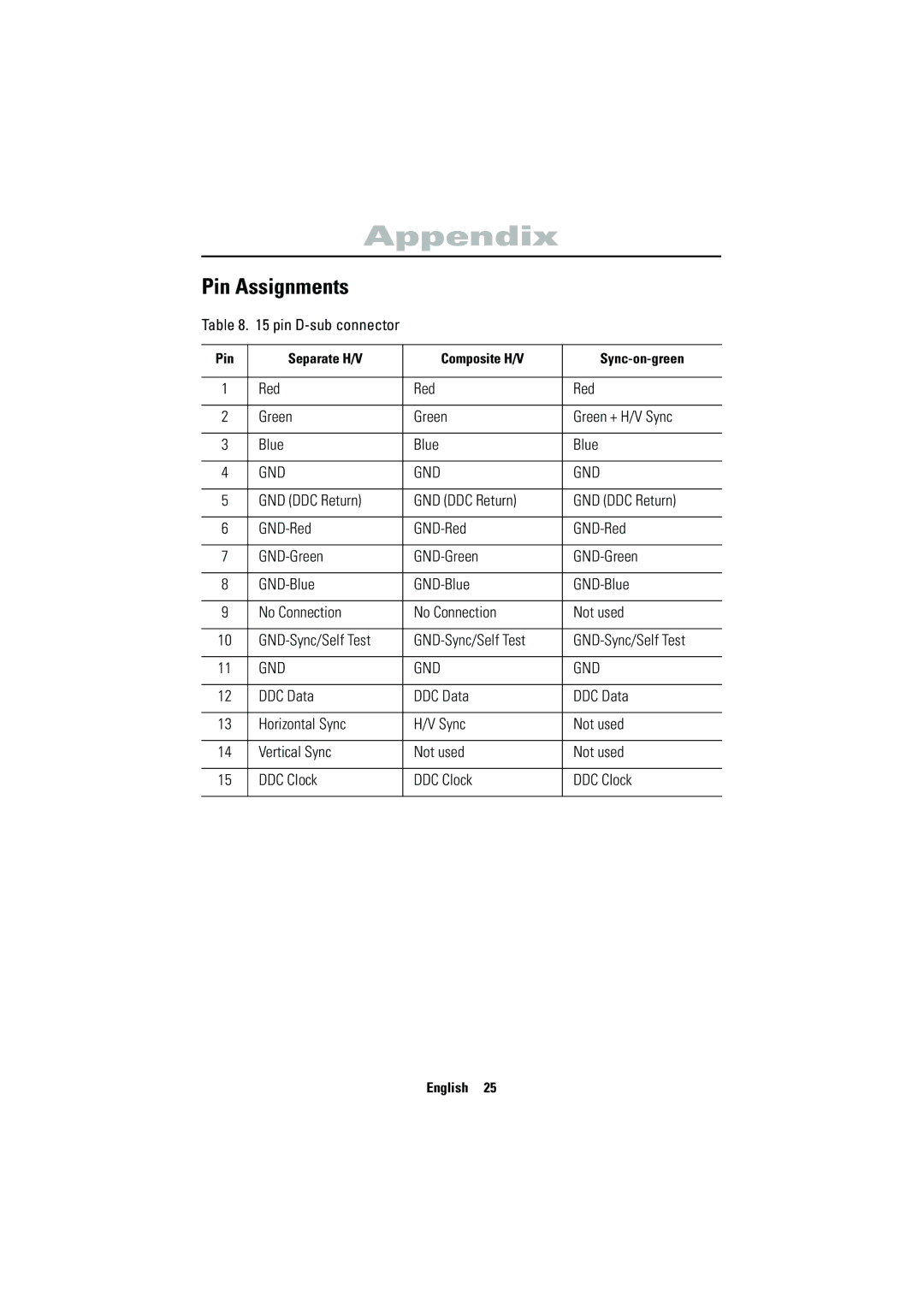
Table 8. 15 pin D-sub connector
Pin | Separate H/V | Composite H/V |
|
|
|
|
|
1 | Red | Red | Red |
|
|
|
|
2 | Green | Green | Green + H/V Sync |
|
|
|
|
3 | Blue | Blue | Blue |
|
|
|
|
4 | GND | GND | GND |
|
|
|
|
5 | GND (DDC Return) | GND (DDC Return) | GND (DDC Return) |
|
|
|
|
6 | |||
|
|
|
|
7 | |||
|
|
|
|
8 | |||
|
|
|
|
9 | No Connection | No Connection | Not used |
|
|
|
|
10 | |||
|
|
|
|
11 | GND | GND | GND |
|
|
|
|
12 | DDC Data | DDC Data | DDC Data |
|
|
|
|
13 | Horizontal Sync | H/V Sync | Not used |
|
|
|
|
14 | Vertical Sync | Not used | Not used |
|
|
|
|
15 | DDC Clock | DDC Clock | DDC Clock |
|
|
|
|
English 25
