2 HARDWARE IMPLEMENTATION | |
|
|
2.2 POWER SUPPLY
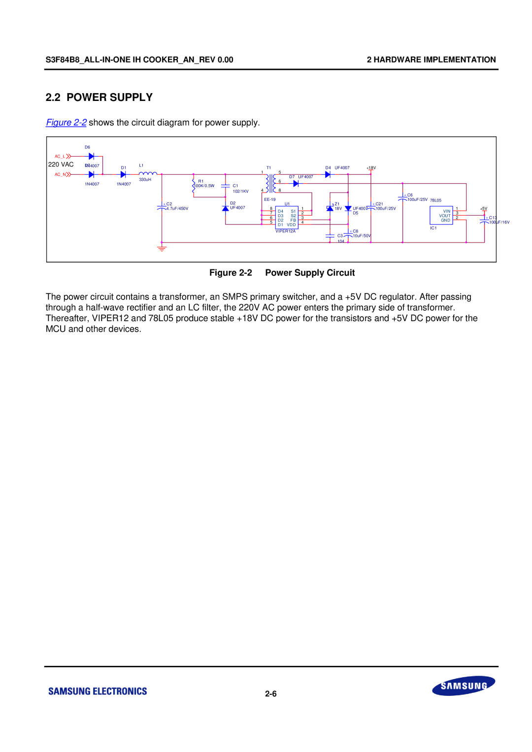
Figure 2-2 shows the circuit diagram for power supply.
| D6 |
|
|
|
|
|
|
|
|
|
|
|
|
|
|
AC_L |
|
|
|
|
|
|
|
|
|
|
|
|
|
|
|
220 VAC | 1N4007D7 | D1 | L1 |
|
| T1 |
|
| D4 | UF4007 | +18V |
|
|
| |
AC_N |
|
|
|
|
| 1 | 5 | D7 | UF4007 |
|
|
|
|
|
|
|
| 330uH |
|
|
|
|
|
|
|
|
|
| |||
|
|
| R1 |
|
| 6 |
|
|
|
|
|
| |||
| 1N4007 | 1N4007 |
|
|
|
|
|
|
|
|
|
| |||
|
| C1 |
|
|
|
|
|
|
|
|
| ||||
|
| 100K/0.5W |
|
|
|
|
|
|
|
|
|
| |||
|
|
|
| 4 | 8 |
|
|
|
|
|
|
|
| ||
|
|
|
|
| 102/1KV |
|
|
|
| + C6 |
|
|
| ||
|
|
|
|
|
|
|
|
|
|
|
|
|
| ||
|
|
|
| + C2 | D2 |
| U1 |
| Z1 |
| 100uF/25V | 78L05 |
|
| |
|
|
|
|
|
|
|
| + C21 |
|
|
| ||||
|
|
|
| 4.7uF/450V | UF4007 | 8 | D4 | S1 | 1 | 18V | UF4007 | 100uF/25V | VIN | 1 | +5V |
|
|
|
|
|
| 7 | 2 |
| D5 |
| 3 |
| |||
|
|
|
|
|
| D3 | S2 |
|
| VOUT |
| ||||
|
|
|
|
|
| 6 | 3 |
|
|
| 2 | + C13 | |||
|
|
|
|
|
| D2 | FB |
|
|
| GND | ||||
|
|
|
|
|
| 5 | D1 | VDD | 4 |
|
|
|
|
| 100uF/16V |
|
|
|
|
|
|
|
|
|
|
| IC1 |
|
| ||
|
|
|
|
|
|
| VIPER12A |
|
| + C8 |
|
|
| ||
|
|
|
|
|
|
|
| C3 |
|
|
|
| |||
|
|
|
|
|
|
|
|
|
| 10uF/50V |
|
|
|
| |
|
|
|
|
|
|
|
|
|
| 104 |
|
|
|
|
|
Figure 2-2 Power Supply Circuit
The power circuit contains a transformer, an SMPS primary switcher, and a +5V DC regulator. After passing through a