3 SOFTWARE IMPLEMENTATION | |
|
|
3.2 SOFTWARE DIAGRAM
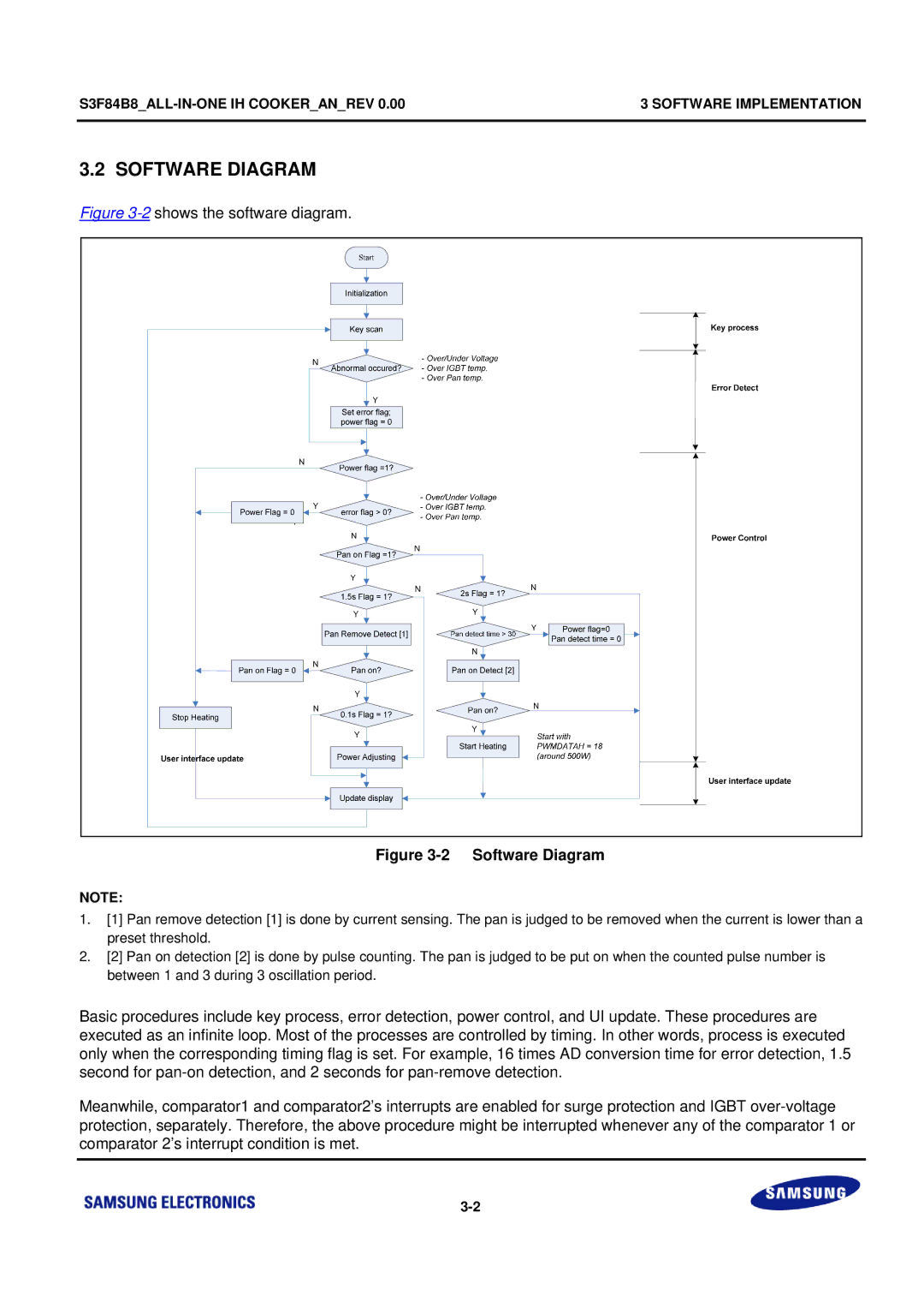
Figure 3-2 shows the software diagram.
Figure 3-2 Software Diagram
NOTE:
1.[1] Pan remove detection [1] is done by current sensing. The pan is judged to be removed when the current is lower than a preset threshold.
2.[2] Pan on detection [2] is done by pulse counting. The pan is judged to be put on when the counted pulse number is between 1 and 3 during 3 oscillation period.
Basic procedures include key process, error detection, power control, and UI update. These procedures are executed as an infinite loop. Most of the processes are controlled by timing. In other words, process is executed only when the corresponding timing flag is set. For example, 16 times AD conversion time for error detection, 1.5 second for
Meanwhile, comparator1 and comparator2’s interrupts are enabled for surge protection and IGBT