2 HARDWARE IMPLEMENTATION | |
|
|
2.4.2 CURRENT MEASUREMENT
SYS_I | R4 | 1K |
| OPA_N |
|
|
|
|
|
|
|
| C10 |
|
|
|
|
| Rf |
|
| RW1 |
|
|
|
|
|
| |
|
| 104J | OPA_O |
| CURRENT |
|
| ||
|
| R13 36K | R14 100K | R1 | OPA _N | ||||
|
|
|
|
|
|
|
|
| |
|
| 10K |
|
| R15 | + |
|
| OPA _O |
|
|
|
| C12 |
| OPA _P | |||
|
|
|
|
| 22K |
|
|
| |
|
|
|
|
|
|
| 1uF/16V |
|
|
|
|
|
|
|
|
|
|
| 3F84B8S |
|
|
|
|
|
|
|
|
| |
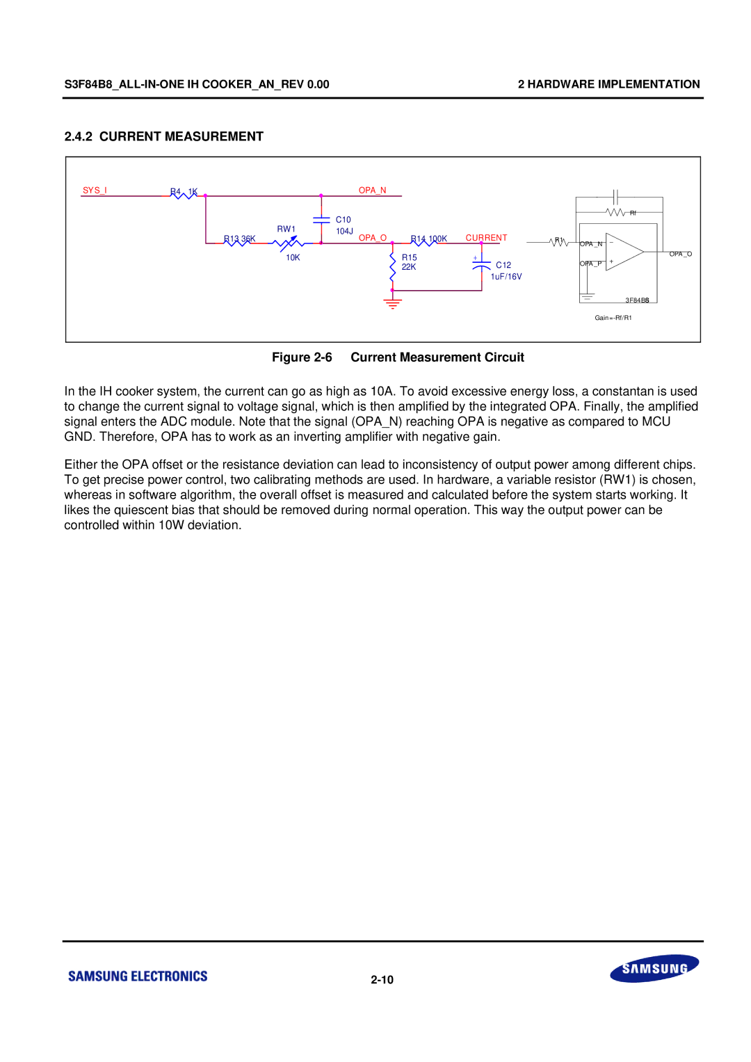
Figure 2-6 Current Measurement Circuit
In the IH cooker system, the current can go as high as 10A. To avoid excessive energy loss, a constantan is used to change the current signal to voltage signal, which is then amplified by the integrated OPA. Finally, the amplified signal enters the ADC module. Note that the signal (OPA_N) reaching OPA is negative as compared to MCU GND. Therefore, OPA has to work as an inverting amplifier with negative gain.
Either the OPA offset or the resistance deviation can lead to inconsistency of output power among different chips. To get precise power control, two calibrating methods are used. In hardware, a variable resistor (RW1) is chosen, whereas in software algorithm, the overall offset is measured and calculated before the system starts working. It likes the quiescent bias that should be removed during normal operation. This way the output power can be controlled within 10W deviation.