3 SOFTWARE IMPLEMENTATION | |
|
|
3 SOFTWARE IMPLEMENTATION
3.1 STATE TRANSITION DIAGRAM
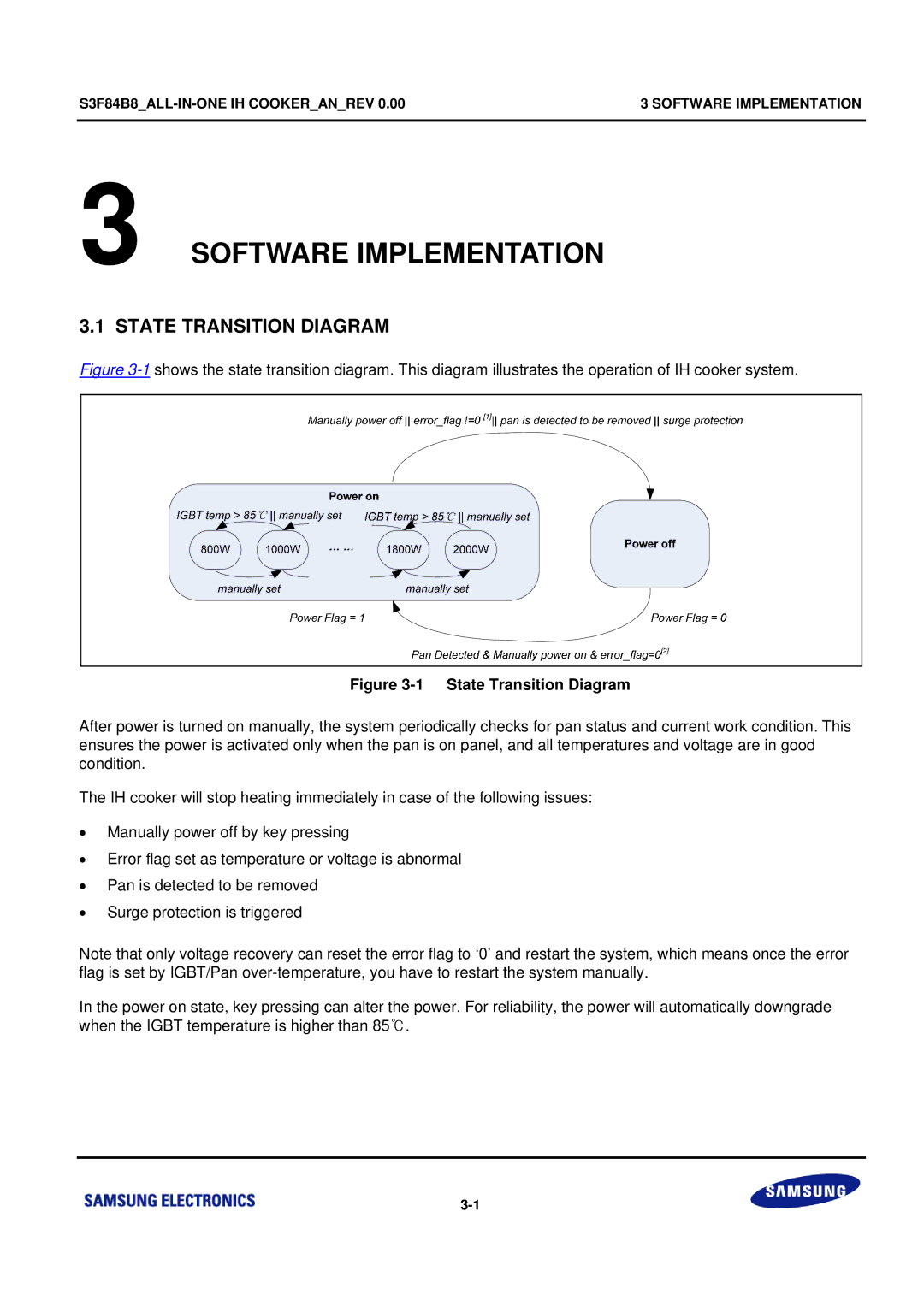
Figure 3-1 shows the state transition diagram. This diagram illustrates the operation of IH cooker system.
Figure 3-1 State Transition Diagram
After power is turned on manually, the system periodically checks for pan status and current work condition. This ensures the power is activated only when the pan is on panel, and all temperatures and voltage are in good condition.
The IH cooker will stop heating immediately in case of the following issues:
∙Manually power off by key pressing
∙Error flag set as temperature or voltage is abnormal
∙Pan is detected to be removed
∙Surge protection is triggered
Note that only voltage recovery can reset the error flag to ‘0’ and restart the system, which means once the error flag is set by IGBT/Pan
In the power on state, key pressing can alter the power. For reliability, the power will automatically downgrade when the IGBT temperature is higher than 85℃.