3 SOFTWARE IMPLEMENTATION | |
|
|
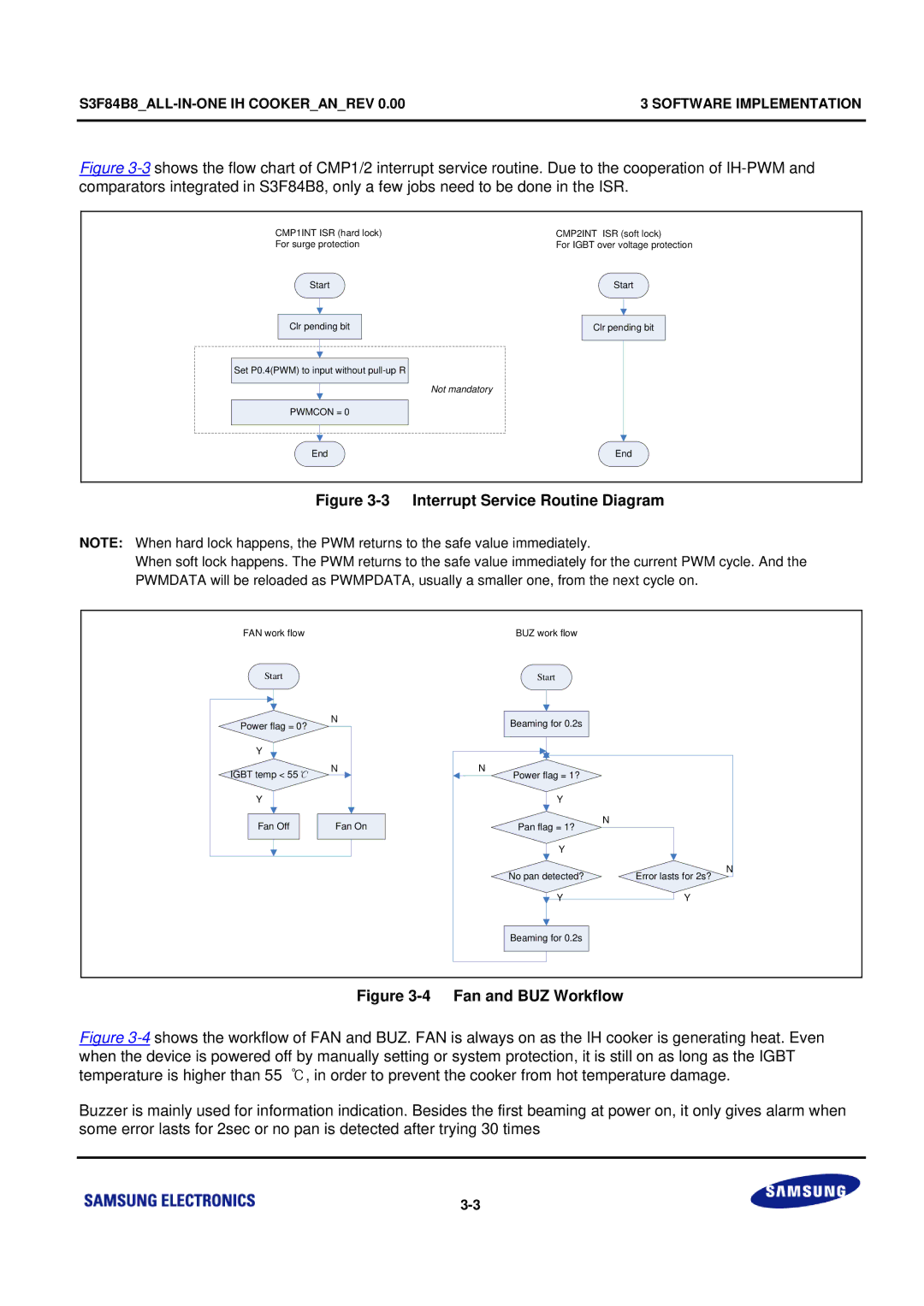
Figure 3-3 shows the flow chart of CMP1/2 interrupt service routine. Due to the cooperation of IH-PWM and comparators integrated in S3F84B8, only a few jobs need to be done in the ISR.
CMP1INT ISR (hard lock)
For surge protection
Start
Clr pending bit
Set P0.4(PWM) to input without
PWMCON = 0
End
CMP2INT ISR (soft lock)
For IGBT over voltage protection
Start
Clr pending bit
Not mandatory
End
Figure 3-3 Interrupt Service Routine Diagram
NOTE: When hard lock happens, the PWM returns to the safe value immediately.
When soft lock happens. The PWM returns to the safe value immediately for the current PWM cycle. And the PWMDATA will be reloaded as PWMPDATA, usually a smaller one, from the next cycle on.
FAN work flow | BUZ work flow |
Start |
|
Power flag = 0? | N |
| |
Y |
|
IGBT temp < 55 | N |
| |
Y |
|
Fan Off | Fan On |
Start
Beaming for 0.2s
N | Power flag = 1? |
|
|
|
|
| |
| Y |
|
|
| Pan flag = 1? | N |
|
|
|
| |
| Y |
|
|
| No pan detected? | Error lasts for 2s? | N |
|
| ||
| Y | Y |
|
| Beaming for 0.2s |
|
|