TECHNICAL DATA
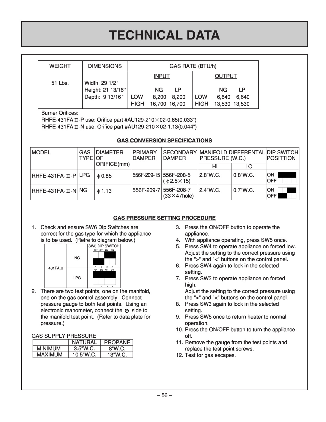
WEIGHT | DIMENSIONS |
|
| GAS RATE (BTU/h) |
| ||
|
|
|
|
|
| ||
|
|
| INPUT |
| OUTPUT | ||
51 Lbs. | Width: 29 1/2" |
|
|
|
|
|
|
| Height: 21 13/16" |
| NG | LP |
| NG | LP |
| Depth: 9 13/16" | LOW | 8,200 | 8,200 | LOW | 6,640 | 6,640 |
|
| HIGH | 16,700 | 16,700 | HIGH | 13,530 | 13,530 |
|
|
|
|
|
|
|
|
Burner Orifices:
![]() -P
-P
![]() -N
-N
GAS CONVERSION SPECIFICATIONS
MODEL |
| GAS | DIAMETER | PRIMARY | SECONDARY | MANIFOLD DIFFERENTAL | DIP SWITCH | |||||||
|
| TYPE | OF | DAMPER | DAMPER | PRESSURE (W.C.) | POSITTION | |||||||
|
|
| ORIFICE(mm) |
|
|
|
|
|
|
|
|
|
|
|
|
|
|
|
| HI | LO |
|
|
|
|
|
|
| |
|
|
|
|
|
|
|
|
|
|
|
|
| ||
LPG | 0.85 | 2.8"W.C. | 0.8"W.C. | ON |
|
|
|
|
| |||||
|
|
|
|
| ||||||||||
|
|
|
|
| ( 2.5×15) |
|
| OFF |
|
|
|
|
| |
|
|
|
|
|
|
|
|
|
|
|
|
|
|
|
NG | 1.13 | 2.4"W.C. | 0.7"W.C. | ON |
|
|
|
|
|
| ||||
|
|
|
|
|
| |||||||||
|
|
|
|
| (33×47hole) |
|
| OFF |
|
|
|
|
|
|
|
|
|
|
|
|
|
|
|
|
|
|
| ||
|
|
|
|
|
|
|
|
|
|
|
|
|
|
|
GAS PRESSURE SETTING PROCEDURE
1.Check and ensure SW6 Dip Switches are correct for the gas type for which the appliance is to be used. (Refre to diagram below.)
|
| SW6 DIP SWITCH | |||||
|
|
| OFF OFF | ON | ON | ||
| NG |
|
|
|
|
|
|
|
|
|
|
|
|
|
|
431FA |
| 1 | 2 | 3 | 4 |
| |
|
| ON | ON | ON | ON | ||
|
|
| |||||
| LPG |
|
|
|
|
|
|
|
|
|
|
|
|
| |
|
|
|
|
|
|
|
|
|
| 1 | 2 | 3 | 4 |
| |
2.There are two test points, one on the manifold, one on the gas control assembly. Connect pressure gauge to both test points. Using an
electronic manometer, connect the ![]() side to the manifold test point. (Refer to data plate for pressure.)
side to the manifold test point. (Refer to data plate for pressure.)
GAS SUPPLY PRESSURE
| NATURAL | PROPANE |
MINIMUM | 3.5"W.C. | 8"W.C. |
MAXIMUM | 10.5"W.C. | 13"W.C. |
3.Press the ON/OFF button to operate the appliance.
4.With appliance operating, press SW5 once.
5.Press SW4 to operate appliance on forced low. Adjust the setting to the correct pressure using the ">" and "<" buttons on the control panel.
6.Press SW4 again to lock in the selected setting.
7.Press SW3 to operate appliance on forced high.
Adjust the setting to the correct pressure using the ">" and "<" buttons on the control panel.
8.Press SW3 again to lock in the selected setting.
9.Press SW5 once to return heater to normal operation.
10.Press the ON/OFF button to turn the appliance off.
11.Remove the gauge from the test points and replace the test point screws.
12.Test for gas escapes.
– 56 –