●RELIABILITY PREDICTION
Solid tantalum capacitors exhibit no degration failure mode during shelf storage and show a constantly decreasing failure rate(i.e. , absence of wearout mechanism) during life tests. this failure rate is dependent upon three important application conditions:DCvoltage, temperature, and circuit impedance.
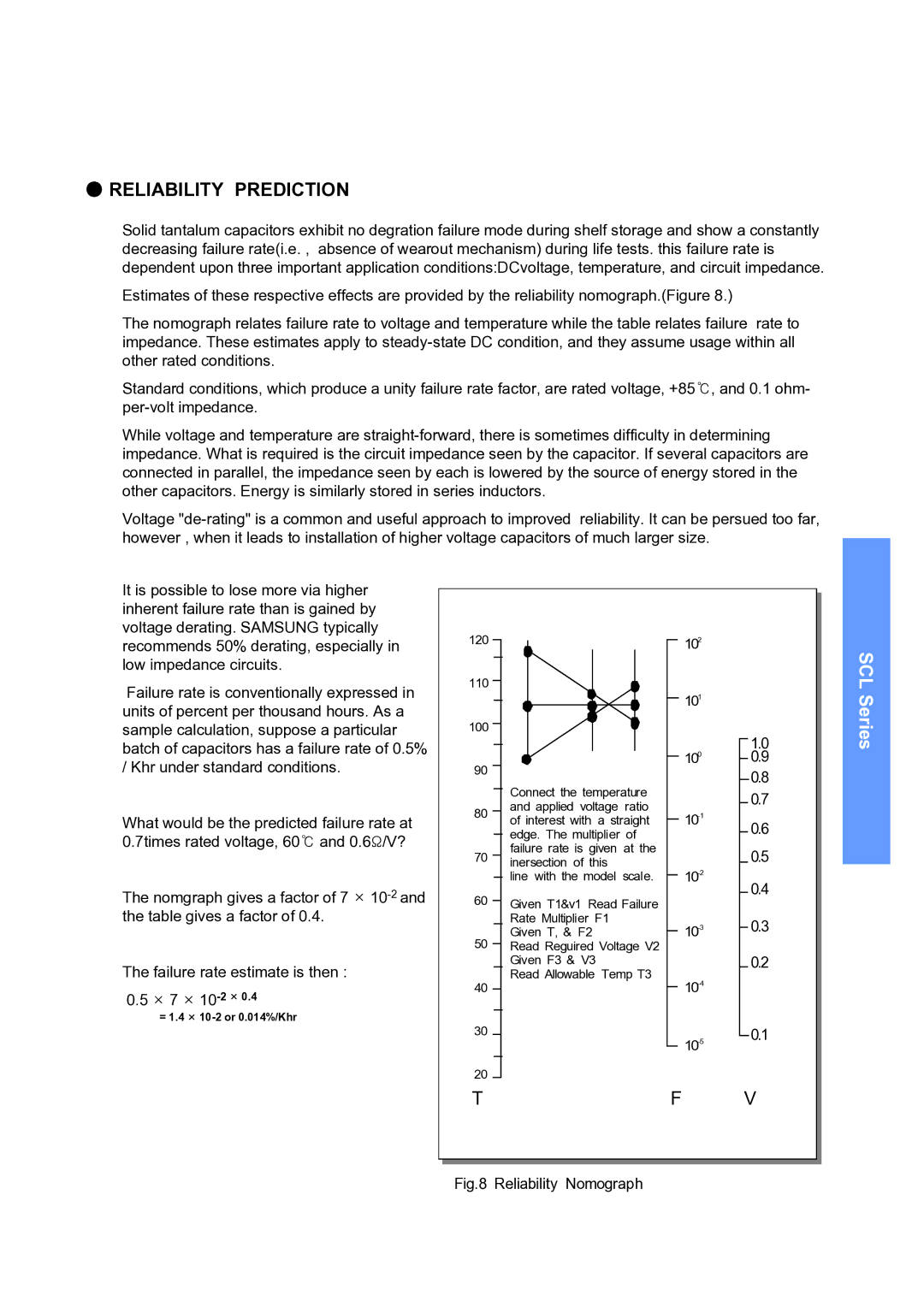
Estimates of these respective effects are provided by the reliability nomograph.(Figure 8.)
The nomograph relates failure rate to voltage and temperature while the table relates failure rate to impedance. These estimates apply to
Standard conditions, which produce a unity failure rate factor, are rated voltage, +85℃, and 0.1 ohm-
While voltage and temperature are
Voltage
It is possible to lose more via higher inherent failure rate than is gained by voltage derating. SAMSUNG typically recommends 50% derating, especially in low impedance circuits.
Failure rate is conventionally expressed in units of percent per thousand hours. As a sample calculation, suppose a particular batch of capacitors has a failure rate of 0.5% / Khr under standard conditions.
What would be the predicted failure rate at 0.7times rated voltage, 60℃ and 0.6Ω/V?
The nomgraph gives a factor of 7 ×
The failure rate estimate is then :
0.5× 7 ×
=1.4 ×
120
110
100
90
80
70
60
50
40
30
20
T
| 102 |
| 101 |
| 100 |
Connect the temperature |
|
and applied voltage ratio | |
of interest with a straight | |
edge. The multiplier of |
|
failure rate is given at the |
|
inersection of this | |
line with the model scale. | |
Given T1&v1 Read Failure |
|
Rate Multiplier F1 | |
Given T, & F2 | |
Read Reguired Voltage V2 |
|
Given F3 & V3 |
|
Read Allowable Temp T3 | |
| |
|
F
1.0
0.9
0.8
0.7
0.6
0.5
0.4
0.3
0.2
0.1
V
SCL Series