Digital Multiplexer
Rear panel
ENGLISH
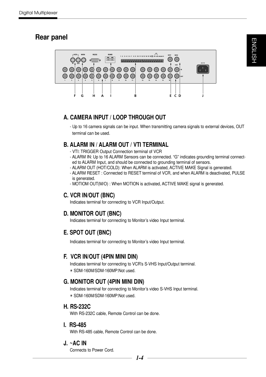
F G H A IBE C DJ
A. CAMERA INPUT / LOOP THROUGH OUT
-Up to 16 camera signals can be input. When transmitting camera signals to external devices, OUT terminal can be used.
B.ALARM IN / ALARM OUT / VTI TERMINAL
-VTI: TRIGGER Output Connection terminal of VCR
-ALARM IN: Up to 16 ALARM Sensors can be connected. “G” indicates grounding terminal connect- ed to ALARM Input, and should be connected to grounding terminal of sensors.
-ALARM OUT (HOT/COLD): When ALARM is activated, ACTIVE MAKE Signal is generated.
-ALARM RESET : Connected to RESET terminal of VCR, and when ALARM is deactivated, PULSE is generated.
-MOTIOM OUT(M/O) : When MOTION is activated, ACTIVE MAKE signal is generated.
C.VCR IN/OUT (BNC)
Indicates terminal for connecting to VCR Input/Output.
D. MONITOR OUT (BNC)
Indicates terminal for connecting to Monitor’s video Input terminal.
E. SPOT OUT (BNC)
Indicates terminal for connecting to Monitor’s video Input terminal.
F. VCR IN/OUT (4PIN MINI DIN)
Indicates terminal for connecting to VCR’s
✴
G.MONITOR OUT (4PIN MINI DIN)
Indicates terminal for connecting to Monitor’s video
✴
H.
With RS-232C cable, Remote Control can be done.
I.
With RS-485 cable, Remote Control can be done.
J. ~AC IN