1 CHAPTER ONE
Connecting The Set Top Box
Digital Ready TV or Normal TV
Connect an antenna cable to the
1 ANT/CABLE IN jacks on the SetTop Box.
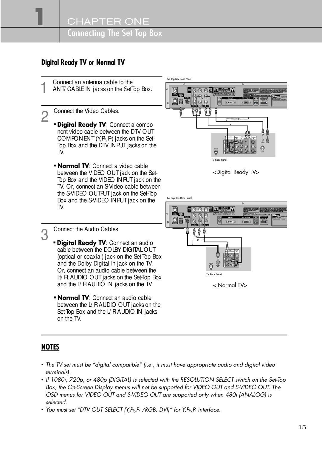
2 Connect the Video Cables.
![]() Digital Ready TV: Connect a compo- nent video cable between the DTV OUT COMPONENT (Y,Pb,Pr) jacks on the Set- Top Box and the DTV INPUT jacks on the TV.
Digital Ready TV: Connect a compo- nent video cable between the DTV OUT COMPONENT (Y,Pb,Pr) jacks on the Set- Top Box and the DTV INPUT jacks on the TV.
![]() Normal TV: Connect a video cable between the VIDEO OUT jack on the Set- Top Box and the VIDEO INPUT jack on the TV. Or, connect an
Normal TV: Connect a video cable between the VIDEO OUT jack on the Set- Top Box and the VIDEO INPUT jack on the TV. Or, connect an
3 Connect the Audio Cables
![]() Digital Ready TV: Connect an audio cable between the DOLBY DIGITAL OUT (optical or coaxial) jack on the
Digital Ready TV: Connect an audio cable between the DOLBY DIGITAL OUT (optical or coaxial) jack on the
![]() Normal TV: Connect an audio cable between the L/R AUDIO OUT jacks on the
Normal TV: Connect an audio cable between the L/R AUDIO OUT jacks on the
<Digital Ready TV>
< Normal TV>
NOTES
•The TV set must be “digital compatible” (i.e., it must have appropriate audio and digital video terminals).
•If 1080i, 720p, or 480p (DIGITAL) is selected with the RESOLUTION SELECT switch on the
•You must set “DTV OUT SELECT (Y,Pb,Pr /RGB, DVI)” for Y,Pb,Pr interface.
15