Section 7 | R |
2.Raise the mower deck to the highest position. Place the lanyard pin in the highest cutting height position to prevent the cutter deck from falling.
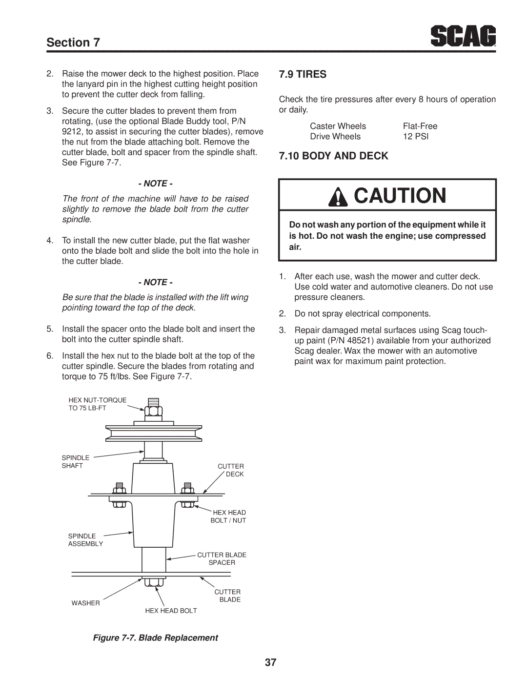
3.Secure the cutter blades to prevent them from rotating, (use the optional Blade Buddy tool, P/N 9212, to assist in securing the cutter blades), remove the nut from the blade attaching bolt. Remove the cutter blade, bolt and spacer from the spindle shaft. See Figure
- NOTE -
The front of the machine will have to be raised slightly to remove the blade bolt from the cutter spindle.
4.To install the new cutter blade, put the flat washer onto the blade bolt and slide the bolt into the hole in the cutter blade.
- NOTE -
Be sure that the blade is installed with the lift wing pointing toward the top of the deck.
5.Install the spacer onto the blade bolt and insert the bolt into the cutter spindle shaft.
6.Install the hex nut to the blade bolt at the top of the cutter spindle. Secure the blades from rotating and torque to 75 ft/lbs. See Figure
HEX
TO 75
SPINDLE
SHAFTCUTTER ![]() DECK
DECK
![]() HEX HEAD
HEX HEAD
BOLT / NUT
SPINDLE
ASSEMBLY
| CUTTER BLADE |
| SPACER |
| CUTTER |
WASHER | BLADE |
| |
| HEX HEAD BOLT |
7.9 TIRES
Check the tire pressures after every 8 hours of operation or daily.
Caster Wheels | |
Drive Wheels | 12 PSI |
7.10 Body and deck
![]() Caution
Caution
Do not wash any portion of the equipment while it is hot. Do not wash the engine; use compressed air.
1.After each use, wash the mower and cutter deck. Use cold water and automotive cleaners. Do not use pressure cleaners.
2.Do not spray electrical components.
3.Repair damaged metal surfaces using Scag touch- up paint (P/N 48521) available from your authorized Scag dealer. Wax the mower with an automotive paint wax for maximum paint protection.
Figure 7-7. Blade Replacement
37
