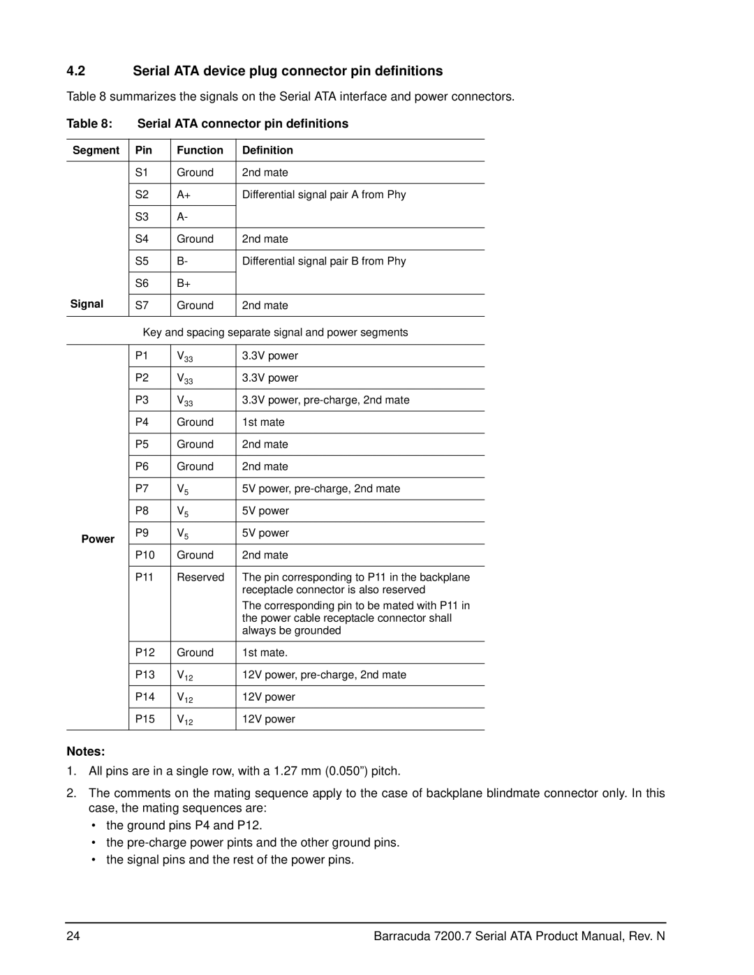
4.2Serial ATA device plug connector pin definitions
Table 8 summarizes the signals on the Serial ATA interface and power connectors.
Table 8: | Serial ATA connector pin definitions | ||
|
|
|
|
Segment | Pin | Function | Definition |
|
|
|
|
| S1 | Ground | 2nd mate |
|
|
|
|
| S2 | A+ | Differential signal pair A from Phy |
|
|
|
|
| S3 | A- |
|
|
|
|
|
| S4 | Ground | 2nd mate |
|
|
|
|
| S5 | B- | Differential signal pair B from Phy |
|
|
|
|
| S6 | B+ |
|
Signal |
|
|
|
S7 | Ground | 2nd mate | |
|
|
|
|
| Key and spacing separate signal and power segments | ||
|
|
|
|
| P1 | V33 | 3.3V power |
| P2 | V33 | 3.3V power |
| P3 | V33 | 3.3V power, |
| P4 | Ground | 1st mate |
|
|
|
|
| P5 | Ground | 2nd mate |
|
|
|
|
| P6 | Ground | 2nd mate |
|
|
|
|
| P7 | V5 | 5V power, |
|
|
|
|
| P8 | V5 | 5V power |
|
|
|
|
Power | P9 | V5 | 5V power |
| P10 | Ground | 2nd mate |
|
|
|
|
| P11 | Reserved | The pin corresponding to P11 in the backplane |
|
|
| receptacle connector is also reserved |
|
|
| The corresponding pin to be mated with P11 in |
|
|
| the power cable receptacle connector shall |
|
|
| always be grounded |
|
|
|
|
| P12 | Ground | 1st mate. |
|
|
|
|
| P13 | V12 | 12V power, |
| P14 | V12 | 12V power |
| P15 | V12 | 12V power |
Notes:
1.All pins are in a single row, with a 1.27 mm (0.050”) pitch.
2.The comments on the mating sequence apply to the case of backplane blindmate connector only. In this case, the mating sequences are:
•the ground pins P4 and P12.
•the
•the signal pins and the rest of the power pins.
24 | Barracuda 7200.7 Serial ATA Product Manual, Rev. N |