3.2Configuring the drive
Each drive on the Serial ATA interface connects in a
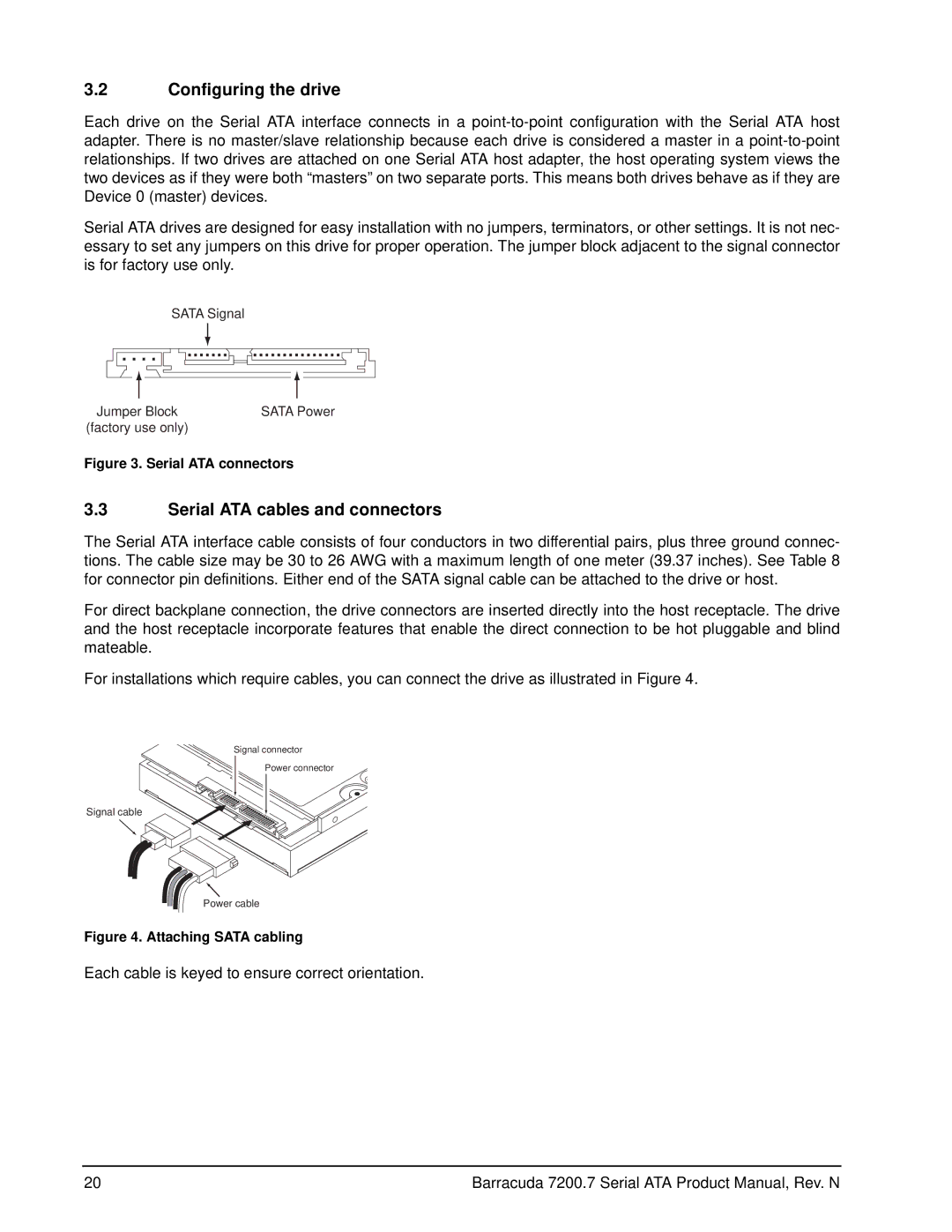
Serial ATA drives are designed for easy installation with no jumpers, terminators, or other settings. It is not nec- essary to set any jumpers on this drive for proper operation. The jumper block adjacent to the signal connector is for factory use only.
SATA Signal
Jumper Block | SATA Power |
(factory use only) |
|
Figure 3. Serial ATA connectors
3.3Serial ATA cables and connectors
The Serial ATA interface cable consists of four conductors in two differential pairs, plus three ground connec- tions. The cable size may be 30 to 26 AWG with a maximum length of one meter (39.37 inches). See Table 8 for connector pin definitions. Either end of the SATA signal cable can be attached to the drive or host.
For direct backplane connection, the drive connectors are inserted directly into the host receptacle. The drive and the host receptacle incorporate features that enable the direct connection to be hot pluggable and blind mateable.
For installations which require cables, you can connect the drive as illustrated in Figure 4.
Signal connector
Power connector
Signal cable
Power cable
Figure 4. Attaching SATA cabling
Each cable is keyed to ensure correct orientation.
20 | Barracuda 7200.7 Serial ATA Product Manual, Rev. N |