Chapter 5 | ATAPI Interface |
ATA registers
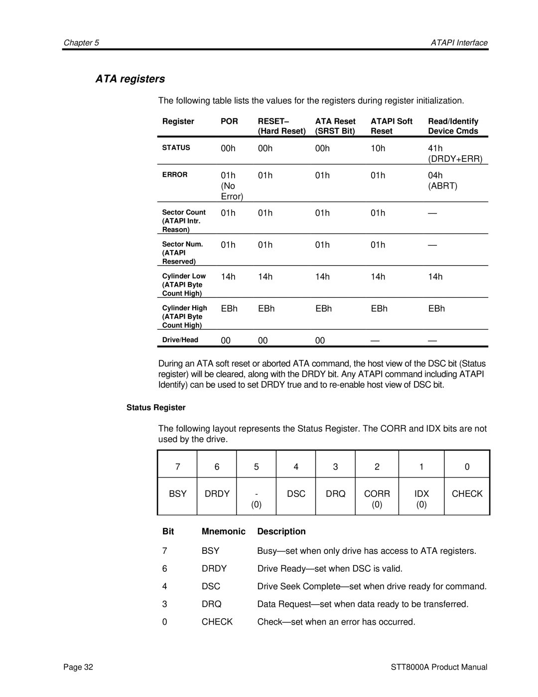
The following table lists the values for the registers during register initialization.
Register | POR | RESET– | ATA Reset | ATAPI Soft | Read/Identify |
|
| (Hard Reset) | (SRST Bit) | Reset | Device Cmds |
STATUS | 00h | 00h | 00h | 10h | 41h |
|
|
|
|
| (DRDY+ERR) |
ERROR | 01h | 01h | 01h | 01h | 04h |
| (No |
|
|
| (ABRT) |
| Error) |
|
|
|
|
Sector Count | 01h | 01h | 01h | 01h | — |
(ATAPI Intr. |
|
|
|
|
|
Reason) |
|
|
|
|
|
Sector Num. | 01h | 01h | 01h | 01h | — |
(ATAPI |
|
|
|
|
|
Reserved) |
|
|
|
|
|
Cylinder Low | 14h | 14h | 14h | 14h | 14h |
(ATAPI Byte |
|
|
|
|
|
Count High) |
|
|
|
|
|
Cylinder High | EBh | EBh | EBh | EBh | EBh |
(ATAPI Byte |
|
|
|
|
|
Count High) |
|
|
|
|
|
Drive/Head | 00 | 00 | 00 | — | — |
During an ATA soft reset or aborted ATA command, the host view of the DSC bit (Status register) will be cleared, along with the DRDY bit. Any ATAPI command including ATAPI Identify) can be used to set DRDY true and to
Status Register
The following layout represents the Status Register. The CORR and IDX bits are not used by the drive.
7 | 6 |
| 5 | 4 | 3 | 2 |
| 1 | 0 |
|
|
|
|
|
|
|
|
|
|
BSY | DRDY |
| - | DSC | DRQ | CORR |
| IDX | CHECK |
|
|
| (0) |
|
| (0) |
| (0) |
|
|
|
|
|
|
|
|
|
|
|
Bit | Mnemonic | Description |
|
|
|
|
| ||
7 | BSY | ||||||||
6 | DRDY | Drive |
|
| |||||
4 | DSC | Drive Seek | |||||||
3 | DRQ | Data | |||||||
0 | CHECK |
|
| ||||||
Page 32 | STT8000A Product Manual |