ATAPI Interface | Chapter 5 |
Error Register
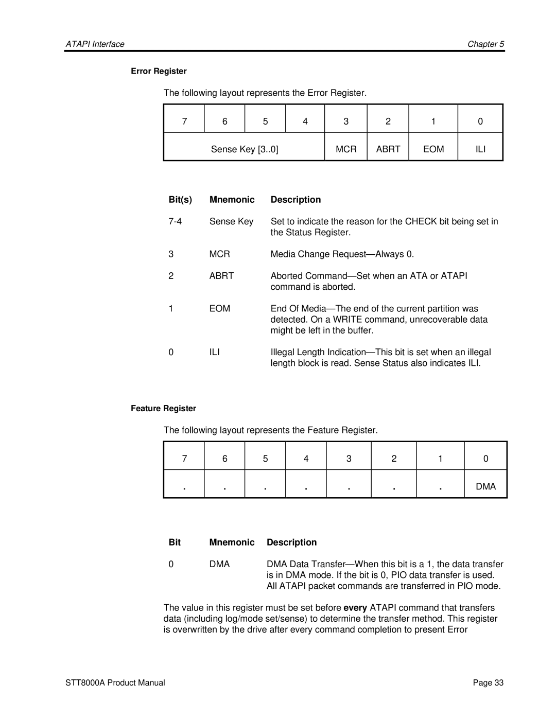
The following layout represents the Error Register.
7 | 6 |
| 5 |
| 4 | 3 |
| 2 |
| 1 |
| 0 |
|
|
|
|
|
|
|
|
|
|
| ||
| Sense Key [3..0] | MCR |
| ABRT |
| EOM |
| ILI | ||||
|
|
|
|
|
|
|
|
|
|
| ||
Bit(s) | Mnemonic |
| Description |
|
|
|
|
|
|
| ||
Sense Key |
| Set to indicate the reason for the CHECK bit being set in | ||||||||||
|
|
|
| the Status Register. |
|
|
|
|
| |||
3 | MCR |
| Media Change |
|
|
| ||||||
2 | ABRT |
| Aborted |
| ||||||||
|
|
|
| command is aborted. |
|
|
|
|
| |||
1 | EOM |
| End Of |
| ||||||||
|
|
|
| detected. On a WRITE command, unrecoverable data | ||||||||
|
|
|
| might be left in the buffer. |
|
|
|
|
| |||
0 | ILI |
| Illegal Length | |||||||||
|
|
|
| length block is read. Sense Status also indicates ILI. | ||||||||
Feature Register
The following layout represents the Feature Register.
7 | 6 | 5 | 4 | 3 | 2 | 1 | 0 |
|
|
|
|
|
|
|
|
. | . | . | . | . | . | . | DMA |
|
|
|
|
|
|
|
|
Bit | Mnemonic | Description |
0 | DMA | DMA Data |
|
| is in DMA mode. If the bit is 0, PIO data transfer is used. |
|
| All ATAPI packet commands are transferred in PIO mode. |
The value in this register must be set before every ATAPI command that transfers data (including log/mode set/sense) to determine the transfer method. This register is overwritten by the drive after every command completion to present Error
STT8000A Product Manual | Page 33 |
