location and function of controls
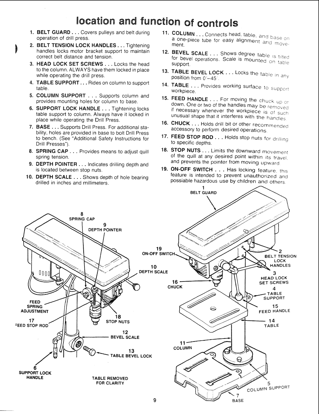
1. | BELT GUARD... Covers pulleys and | belt during |
| operation of drill press, |
|
2. | BELT TENSION LOCK HANDLES... | Tightening |
| handles locks motor bracket support to maintain | |
| correct belt distance and tension. |
|
11. | COLUMN... | Connects | head, tab;le, | and _ |
| ||||
| a | tube for | easy alignmer_t | ar_:_, |
| ment. |
|
|
12,
BEVEL SCALE... Shows degree table _s tied
3. | HEAD | LOCK SET SCREWS... Locks the head |
| to the column. ALWAYS have them locked in place | |
| while operating the drill press, | |
4. | TABLE | SUPPORT,.. Rides on column to support |
| table. |
|
13.
14.
for bevel operations. Scale is mounted on ta_:>e support.
TABLE BEVEL LOCK... Locks the tabie
TABLE ... Provides working surface to supp,::,;t workpiece.
5. | COLUMN SUPPORT . . . Supports column | and | |
| provides mounting holes for column to base. |
| |
6. | SUPPORT LOCK HANDLE... | Tightening | locks |
| table support to column, Always have it locked in | ||
| place while operating the Drill Press. |
| |
7. BASE... Supports Drill Press. For additional sta- bility, holes are provided in base to bolt Drill Press to bench. (See "Additional Safety Instructions for Drill Presses").
8.SPRING CAP... Provides means to adjust quill spring tension.
9.DEPTH POINTER... Indicates drilling depth and is located between stop nuts.
10.DEPTH SCALE... Shows depth of hole bearing drilled in inches and millimeters.
8 SPRING CAP
9
15.FEED HANDLE . .. For moving the chuck _;D o; down. One or two of the handles may be ,_emove_,: if necessary whenever the workpiece is of sucf_ unusual shape that it interferes with the handles
16.CHUCK.., Holds drill bit or other recommer_de(_; accessory to perform desired operations
17.FEED STOP ROD.. , Holds stop nuts for dri!ti_lg to specific depths,
18.STOP NUTS ... Limits the downward movemem of the quill at any desired point within its travel and prevents the pointer from moving upward
19.
feature is intended to prevent unauthorized an(_ possiable hazardous use by children and others.
1
BELT GUARD
DEPTH POINTER
| 19 |
| 2 | |
|
| |||
| }ELT TENSION | |||
|
|
| LOCK | |
| 10 |
| HANDLES | |
|
|
| ||
| DEPTH SCALE |
| 3 | |
|
| HEAD | LOCK | |
| 16 | SETSCREWS | ||
| CHUCK |
| 4 | |
|
| /TABLE |
| |
|
| SUPPORT | ||
FEED |
|
| 15 | |
SPRING |
|
| ||
| FEED | HANDLE | ||
ADJUSTMENT |
| |||
|
|
| ||
17 | 18 | 14 | ||
STOP NUTS | ||||
TABLE | ||||
=EED STOP ROD |
| |||
|
|
| ||
| 12 |
|
| |
| BEVEL SCALE |
|
| |
| COLUMN |
|
| |
| 13 |
|
| |
| TABLE BEVEL LOCK |
|
| |
6 |
|
|
| |
SUPPORT LOCK |
|
|
| |
HANDLE | TABLE REMOVED | 5 | ||
| FOR CLARITY | |||
|
| COLUMN | SUPPORT | |
9
