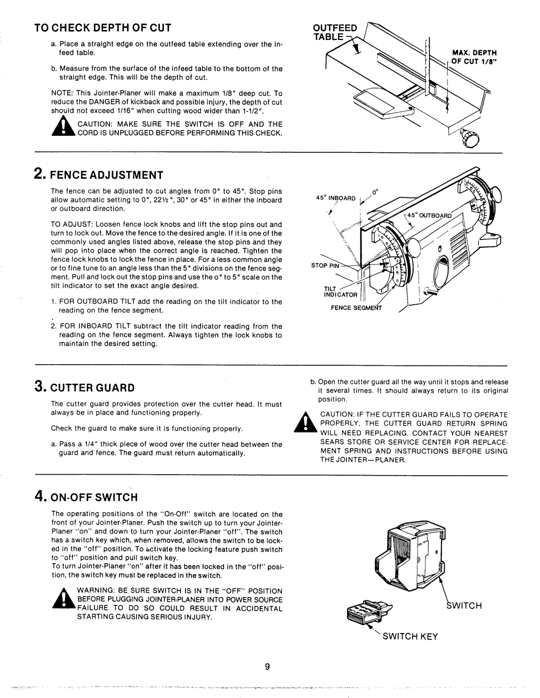
TO CHECK DEPTH OF CUT | OUTFEED | |
|
| TABLE |
a. Place a straight edge on the outfeed table extending over the in- |
| |
feed | table. | MAX. DEPTH |
|
| ,OF CUT 1/8" |
b. Measure from the surface of the infeed table to the bottom of the |
| |
straight edge. This will be the depth of cut. |
| |
| ||
reduce the DANGER of kickback and possible injury, the depth of cut |
| |
should not exceed 1/16" when cutting wood wider than |
| |
,_ | CAUTION: MAKE SURE THE SWITCH IS OFF AND THE |
|
| CORD tS UNPLUGGED BEFORE PERFORMING THIS CHECK. |
|
2. FENCE ADJUSTMENT
The fence can be adjusted to cut angles from 0 ° to 45 °. Stop pins allow automatic setting to 0 °, 221/2 °, 30 ° or 45 ° in either the inboard or outboard direction.
TO ADJUST: Loosen fence lock knobs and lift the stop pins out and turn to lock out. Move the fence to the desired angle. If it is one of the commonly used angles listed above, release the stop pins and they will pop into place when the correct angle is reached. Tighten the fence lock knobs to lock the fence in place. For a less common angle or to fine tune to an angle less than the 5 ° divisions on the fence seg- ment. Pul! and lock out the stop pins and use theo ° to 5 ° scale on the tilt indicator to set the exact angle desired.
1.FOR OUTBOARD TILT add the reading on the tilt indicator to the reading on the fence segment.
2.FOR INBOARD TILT subtract the tilt indicator reading from the reading on the fence segment. Always tighten the lock knobs to maintain the desired setting.
3.CUTTER GUARD
The cutter guard provides protection over the cutter head. It must
always be in place and functioning properly.
Check the guard to make sure it is functioning properly.
a. Pass a !14" thick piece of wood over the cutter head between the guard and fence. The guard must return automatically.
STOP P
TILT
INDICATOR
FENCE
b. Open the cutter guard all the way until it stops and release it several times. It should always return to its original position.
CAUTION: IF THE CUTTER GUARD FAILS TO OPERATE PROPERLY, THE CUTTER GUARD RETURN SPRING WILL NEED REPLACING. CONTACT YOUR NEAREST SEARS STORE OR SERVICE CENTER FOR REPLACE- MENT SPRING AND INSTRUCTIONS BEFORE USING THE
4, ON-OFF SWITCH
The operating positions of the
To turn
,_WARNING: | BE SURE | SWITCH | IS IN THE "OFF" POSITION |
|
BEFORE PLUGGING JOINTER.PLANER INTO POWER SOURCE |
| |||
FAILURE TO DO SO COULD RESULT IN ACCIDENTAL |
| |||
STARTING | CAUSING | SERIOUS | INJURY. | SWITCH |
|
|
|
| |
\ SWITCH KEY
9