PARTS REPLACEMENT
Incline Lever (46e) Replacement
Step 1. Remove two SCREWS (63) at top of CONSOLE TUBE (40).
Step 2. Remove one SCREW (460) on lower rear side of CONSOLE BOTTOM (46b).
Step 3. Pull CONSOLE (46) from CONSOLE TUBE (40) and remove two SCREWS (46n) and remove LOWER CONTROL PANEL (46d) from CONSOLE BOTTOM (46b).
Step 4. Reinsert CONSOLE (46) into CONSOLE TUBE (40) for convenience.
Step 5. Remove two SCREWS (46n) attaching INCLINE BRACKET (46f) to back side of LOWER CONTROL PANEL
(46d).
Step 6. Remove INCLINE LEVER (46e) from PIVOT SLOTS in back side of LOWER CONTROL PANEL (46d).
Step 7. Detach INCLINE LEVER (46e) from INCLINE CABLE (46j) by sliding CABLE END of INCLINE CABLE into upper hole in INCLINE LEVER and pulling through.
Step 8. Reassemble CONSOLE (46) using REPLACEMENT INCLINE LEVER (46e) by following steps 1 through 8 in reverse order.
Gas Cylinder (26) Replacement
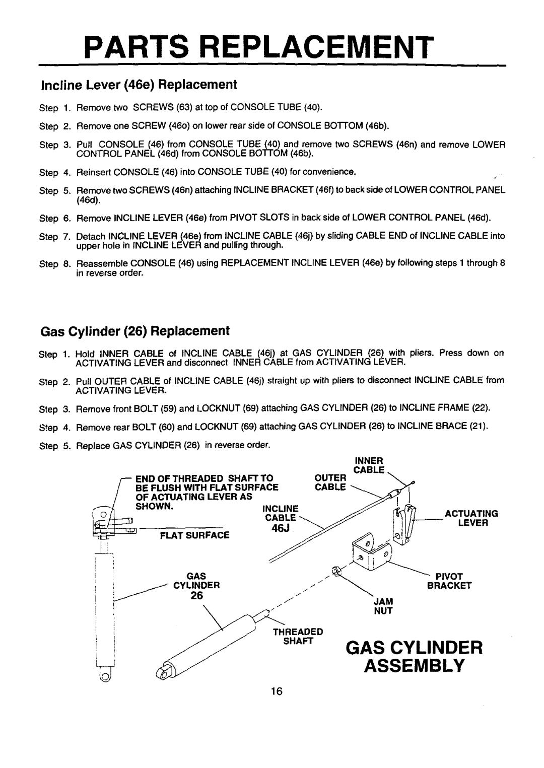
Step 1. Hold INNER CABLE of INCLINE CABLE (46j) at GAS CYLINDER (26) with pliers. Press down on ACTIVATING LEVER and disconnect INNER CABLE from ACTIVATING LEVER.
Step 2. Pull OUTER CABLE of INCLINE CABLE (46j) straight up with pliers to disconnect INCLINE CABLE from
ACTIVATING LEVER.
Step 3. Remove front BOLT (59) and LOCKNUT (69) attaching GAS CYLINDER (26) to INCLINE FRAME (22).
Step 4. Remove rear BOLT (60) and LOCKNUT (69) attaching
Step 5. Replace GAS CYLINDER (26) in reverse order.
END OF THREADED SHAFT TO
BE FLUSH WITH FLAT SURFACE
OF ACTUATING LEVER AS
GAS CYLINDER (26) to INCLINE BRACE (21).
INNER
CABLE
OUTER
CABLE
I o _ | SHOWN. | INCLINE | ACTUATING |
| ABL | LEVER | |
| _E |
| |
| 46J |
|
PIVOT
BRACKET
GAS CYLINDER
ASSEMBLY
16