ASSEMBLY
Place all parts of the exercise cycle in a cleared area and remove the packing materials. Do not dispose of the packing materials until assembly is completed. Assembly requires a phillips screwdriver ![]()
![]()
and an adjustable wrench  (not included).
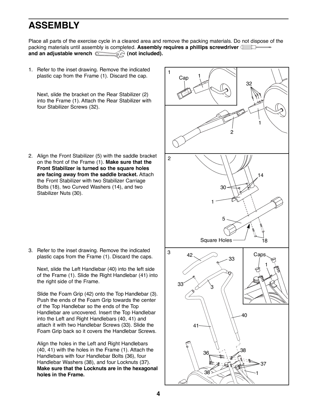
1.Refer to the inset drawing. Remove the indicated plastic cap from the Frame (1). Discard the cap.
Next, slide the bracket on the Rear Stabilizer (2) into the Frame (1). Attach the Rear Stabilizer with four Stabilizer Screws (32).
2.Align the Front Stabilizer (5) with the saddle bracket on the front of the Frame (1). Make sure that the
Front Stabilizer is turned so the square holes are facing away from the saddle bracket. Attach the Front Stabilizer with two Stabilizer Carriage Bolts (18), two Curved Washers (14), and two Stabilizer Nuts (30).
3.Refer to the inset drawing. Remove the indicated plastic caps from the Frame (1). Discard the caps.
Next, slide the Left Handlebar (40) into the left side of the Frame (1). Slide the Right Handlebar (41) into the right side of the Frame.
Slide the Foam Grip (42) onto the Top Handlebar (3). Push the ends of the Foam Grip towards the center of the Top Handlebar so the ends of the Top Handlebar are uncovered. Insert the Top Handlebar into the Left and Right Handlebars (40, 41) and attach it with two Handlebar Screws (33). Slide the Foam Grip back so it covers the Handlebar Screws.
Align the holes in the Left and Right Handlebars (40, 41) with the holes in the Frame (1). Attach the Handlebars with four Handlebar Bolts (36), four Handlebar Washers (38), and four Locknuts (37).
Make sure that the Locknuts are in the hexagonal holes in the Frame.
1 | Cap | 1 |
|
|
| ||
|
| 32 | |
|
|
| |
|
|
| 1 |
|
| 2 |
|
2 |
|
|
|
|
|
| 14 |
|
| 30 |
|
|
| 1 |
|
|
| 5 |
|
|
| Square Holes | 18 |
3 | 42 |
| Caps |
| 33 | ||
|
| 1 | |
|
|
| |
| 33 | 3 |
|
|
|
| |
|
|
| 40 |
|
| 41 |
|
|
| 36 | 38 |
|
|
| |
|
|
| 37 |
|
| 38 | 1 |
4