UPPER
STEERING
SHAFT
BOLTS
FIGURE 1
SEAT
HE× SHOULDER BOLT 5t!6 - 18 & LOCK NUT
SEAT
/BRACKET
FIGURE 2
J
CLUTCH/BRAK E PEDAL
/
LOWER STEERING
SHAFT
SLEEVE
BRACKET
HEX BOLTS, WASHERS
AND LOCK NUTS
BOLT
5/16 - 18 & LOCK NUT
FENDER
To assemble your Tractor you will need:
two 7/16" wrenches, two 9/16" wrenches, two 1/2" wrenches, a 3/4" wrench and a utility knife
NOTE: RIGHT HAND (R,H) AND LEFT HAND (LH.) ARE
DETERMINED FROM OPERATOR'S POSITION WHILE SEATED ON THE TRACTOR
ASSEM6LY
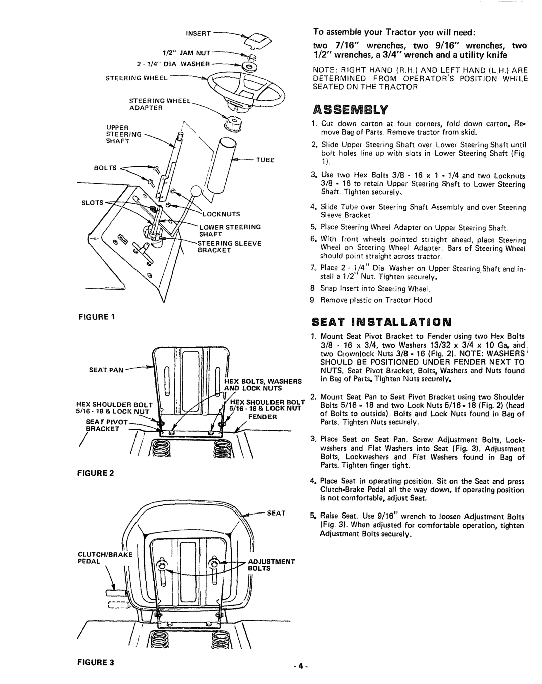
I,. Cut down carton at four corners, fold down carton, Re. move Bag of Parts, Remove tractor from skid,
2, Slide Upper Steering Shaft over Lower Steering Shaft until
boil holes line up with slots in Lower Steering Shaft (Fig, 1),
3_ Use two Hex Bolts 3/8 - 16 x t . 1/4 and two Locknuts
3/8 - 16 to retain Upper Steering Shaft to Lower Steering Shaft Tighten securely.,
4o Stide Tube over Steering Shaft Assembly and over Steering Sleeve Bracket
5_ Place Steering Wheel Adapter on Upper Steering Shaft,
6. With front wheels pointed straight ahead, place Steering Wheel on Steering Wheel
7o Place 2 - 1/4" Dia, Washer on Upper SteeringShaft and in- stall a 1/2" Nut, Tighten securely,
8 Snap Insert into Steering Wheel,
9 Remove plastic on Tractor Hood
SEAT iNSTALLATiON
,Mount Seat Pivot Bracket to Fender using two Hex Bolts 3/8 - 16 x 3/4, two Washers t3/32 x 3/4 x 10 Ga. and,
two Crownlock Nuts 3/8- 16 (Fig, 2). NOTE; WASHERS _
SHOULD BE POSITIONED UNDER FENDER NEXT TO NUTS. Seat Pivot Bracket, Bolts, Washers and Nuts found in Bag of Parts° Tighten Nuts securely.
2.Mount Seat Pan to Seat Pivot Bracket using two Shoulder BOlts 5/16 - 18 and two Lock Nuts 5/16- 18 (Fig. 2) (head of Bolts to outside)_ Bolts and Lock Nuts found in Bag of Parts, Tighten Nuts secureFy,
3_ Place Seat on Seat Pan,. Screw Adjustment Bolts, Lock- washers and Flat Washers into Seat (Fig. 3), Adjustment Bolts, Lockwashers and Flat Washers found in Bag of Parts, Tighten finger'tight,
4_ Place Seat in operating position° Sit on the Seat and press
5.Raise Seat. Use 9/t6" wrench to loosen Adjustment Bolts (Fig, 3), When adjusted for'comfortable operation, tighten Adjustment Bolts securel¥o
FIGURE 3 | - 4 - |
