Manuals
/
Sears
/
Lawn and Garden
/
Lawn Mower
Sears
917.28858
owner manual
Barra Antibalanceo S, Agujero, To Replace Mower Drive Belt
Models:
917.28858
1
28
36
36
Download
36 pages
6.58 Kb
25
26
27
28
29
30
31
32
Troubleshooting
Specs
Install
Lubrication Chart
Assembly
Battery
To Adjust Gauge Wheels
Checklist
Clean Air Screen
How to
Page 28
Image 28
Page 27
Page 29
Page 28
Image 28
Page 27
Page 29
Contents
For answers to your questions
about this product, Call
12.28.11 TH
Sears Craftsman Help Line
TABLE OF CONTENTS
WARRANTY
Craftsman Riding Equipment Warranty
CRAFTSMAN FULL WARRANTY
SERVICE NOTES/AVISO
SAFETY RULES
I. GENERAL OPERATION
after handling
V. SERVICE
II. SLOPE OPERATION
III. CHILDREN
IV. TOWING
GENERAL SERVICE
PRODUCT SPECIFICATIONS
SEARS INSTALLATION SERVICE
CUSTOMER RESPONSIBILITIES
REPAIR PROTECTION AGREEMENTS
UNASSEMBLED PARTS
TRACTOR
BATERÍA
MOTOR
ASSEMBLY/PRE-OPERATION
TOOLS REQUIRED FOR ASSEMBLY
TO INSTALL MOWER
TO CHECK BATTERY
K C I C
M F B L A W E H S D Q
VERIFIQUE EL FRENO
IMPRESIÓN / INCLINACIÓN DE LAS RUEDAS DELANTERAS
ANTI-SWAYBAR S
MOWER DRIVE BELT INSTALLATION
PARA NIVELAR LA SEGADORA
CHECKLIST
SERVICIO Y AJUSTES
CHECK TIRE PRESSURE
CHECK DECK LEVELNESS
PUERTO DE LAVADO DE LA CUBIERTA
OPERATION
ADVERTENCIA Si el accesorio de lavado
KNOW YOUR TRACTOR
HLIGHT SWITCH - Turns the headlights on and off
LIMPIEZA
HOW TO USE YOUR TRACTOR
PARA CAMBIAR EL ACEITE DEL MOTOR
TO SET PARKING BRAKE
STOPPING
TO ADJUST GAUGE WHEELS
TO ADJUST MOWER CUTTING HEIGHT
TO MOVE FORWARD AND BACKWARD
TO USE CRUISE CONTROL
MANTENIMENTO
TO STOP MOWER BLADES
TO OPERATE ON HILLS
REVERSE OPERATION SYSTEM ROS
SERVICE REMINDER/HOUR METER
BEFORE STARTING THE ENGINE
TO START ENGINE
CHECK ENGINE OIL LEVEL
PURGE TRANSMISSION
MOWING TIPS
ANTES DE HACER ARRANCAR EL MOTOR
MAINTENANCE
GENERAL RECOMMENDATIONS
BEFORE EACH USE
MAINTENANCE
BATTERY
TRACTOR
BRAKE OPERATION
TIRES
ENGINE
TO CHANGE ENGINE OIL
COMO USAR SU TRACTOR
V-BELTS
CLEAN AIR SCREEN
CLEAN AIR INTAKE/COOLING AREAS
AIR FILTER
MUFFLER
CLEANING
OPERACIÓN
CAUTION Avoid all pinch points and
movable parts
SERVICE AND ADJUSTMENTS
TO INSTALL MOWER
TO REMOVE MOWER
LB M
PARA REEMPLAZAR LA CORREA DE LA SEGADORA
TO LEVEL MOWER
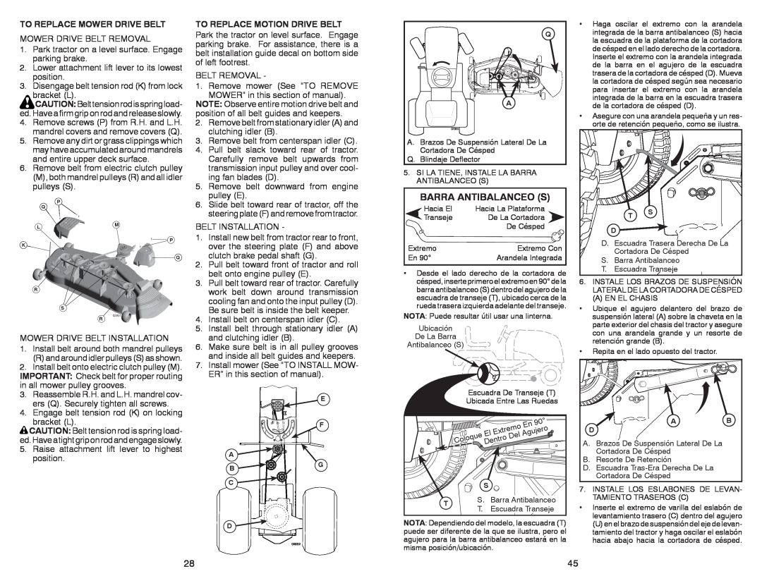
BARRA ANTIBALANCEO S
Agujero
TO REPLACE MOWER DRIVE BELT
TO REPLACE MOTION DRIVE BELT
TO CHECK BRAKE
FRONT WHEEL TOE-IN/CAMBER
TO REMOVE WHEEL FOR REPAIRS
TO START ENGINE WITH A WEAK BAT- TERY
REPLACING BATTERY
TO REMOVE HOOD AND GRILL ASSEMBLY
REMOVAL/REPLACEMENT
TO ADJUST THROTTLE CONTROL CABLE
BATTERY
PIEZAS SIN MONTAR
STORAGE
OTHER
TROUBLESHOOTING CHART
PROBLEM
CAUSE
CORRECTION
Loss of power
run when operator
REGLAS DE SEGURIDAD
Engine clicks but
Poor cut - uneven
cutting
Mower blades will
not rotate
Battery will not
when turning
I. FUNCIONAMIENTO GENERAL
II.FUNCIONAMIENTO EN PENDIENTES
TABLA DE MATERIAS
GARANTÍA
Garantía para equipos tractores Craftsman
GARANTÍA COMPLETA DE CRAFTSMAN
Top
Page
Image
Contents