TRACTOR
Always observe safety rules when performing any maintenance.
BRAKE OPERATION
If tractor requires more than five (5) feet to stop at highest speed in highest gear on a level, dry concrete or paved surface, then brake must be serviced. (See “TO CHECK BRAKE” in the Service and Adjustments section of this manual).
TIRES
•Maintain proper air pressure in all tires (See PSI on tires).
•Keep tires free of gasoline, oil, or insect control chemicals which can harm rub- ber.
•Avoid stumps, stones, deep ruts, sharp objects and other hazards that may cause
tire damage.
NOTE: To seal tire punctures and prevent flat tires due to slow leaks, tire sealant may be purchased from your local parts dealer. Tire sealant also prevents tire dry rot and corrosion.
OPERATOR PRESENCE SYSTEM AND REVERSE OPERATION SYSTEM (ROS)
Be sure operator presence and reverse operation systems are working properly. If your tractor does not function as described, repair the problem immediately.
•The engine should not start unless the brake pedal is fully depressed, and the attachment clutch control is in the disen- gaged position.
CHECK OPERATOR PRESENCE SYSTEM
• When the engine is running, any attempt |
by the operator to leave the seat without |
first setting the parking brake should shut |
off the engine. |
• When the engine is running and the at- |
tachment clutch is engaged, any attempt |
by the operator to leave the seat should |
CHECK REVERSE OPERATION (ROS) SYSTEM
•When the engine is running with the ignition switch in the engine "ON" position and the attachment clutch engaged, any attempt by the operator to shift into reverse should shut off the engine.
•When the engine is running with the ignition switch in the ROS "ON" position and the attachment clutch engaged, any attempt by the operator to shift into reverse should NOT shut off the engine.
BLADE CARE
For best results mower blades must be sharp. Replace worn, bent or damaged blades.  CAUTION: Use only a replacement blade approved by the manufacturer of your tractor. Using a blade not approved by the manu- facturer of your tractor is hazardous, could damage your tractor and void your warranty.
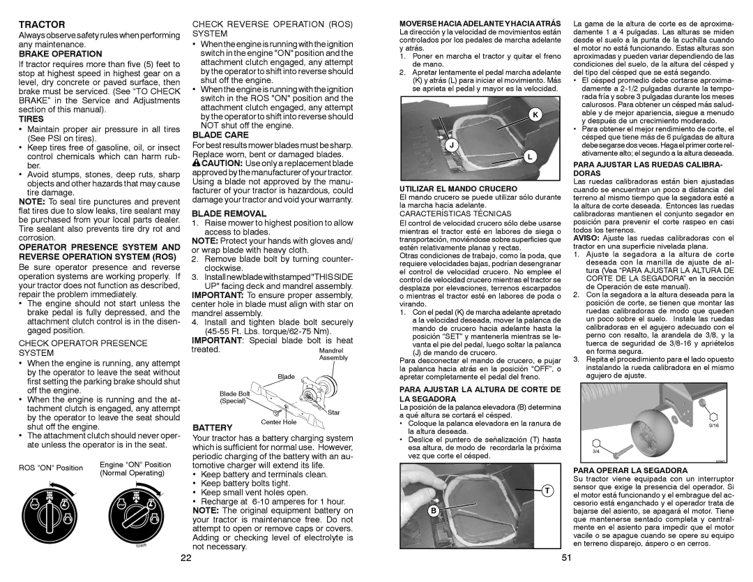
BLADE REMOVAL
1.Raise mower to highest position to allow access to blades.
NOTE: Protect your hands with gloves and/ or wrap blade with heavy cloth.
2.Remove blade bolt by turning counter- clockwise.
3.Installnewbladewithstamped"THISSIDE
UP" facing deck and mandrel assembly. IMPORTANT: To ensure proper assembly, center hole in blade must align with star on mandrel assembly.
4.Install and tighten blade bolt securely (45-55 Ft. Lbs. torque/62-75 Nm).
IMPORTANT: Special blade bolt is heat treated.
Blade
Blade Bolt | |
(Special) | |
0 | 2545 |
|
| Star |
MOVERSE HACIA ADELANTE Y HACIA ATRÁS
La dirección y la velocidad de movimientos están controlados por los pedales de marcha adelante y atrás.
1.Poner en marcha el tractor y quitar el freno de mano.
2.Apretar lentamente el pedal marcha adelante
(K) y atrás (L) para iniciar el movimiento. Más se aprieta el pedal y mayor es la velocidad.
UTILIZAR EL MANDO CRUCERO
El mando crucero se puede utilizar sólo durante la marcha hacia adelante.
CARACTERÍSTICAS TÉCNICAS
El control de velocidad crucero sólo debe usarse mientras el tractor esté en labores de siega o transportación, moviéndose sobre superficies que estén relativamente planas y rectas.
Otras condiciones de trabajo, como la poda, que requiere velocidades bajas, podrían desengranar el control de velocidad crucero. No emplee el control de velocidad crucero mientras el tractor se desplaza por elevaciones, terrenos escarpados o mientras el tractor esté en labores de poda o virando.
1.Con el pedal (K) de marcha adelante apretado a la velocidad deseada, mover la palanca de mando de crucero hacia adelante hasta la posición “SET” y mantenerla mientras se le- vanta el pie del pedal, luego soltar la palanca
(J) de mando de crucero.
Para desconectar el mando de crucero, e pujar la palanca hacia atrás en la posición “OFF”, o apretar completamente el pedal del freno.
PARA AJUSTAR LA ALTURA DE CORTE DE LA SEGADORA
La posición de la palanca elevadora (B) determina a qué altura se cortará el césped.
La gama de la altura de corte es de aproxima- damente 1 a 4 pulgadas. Las alturas se miden desde el suelo a la punta de la cuchilla cuando el motor no está funcionando. Estas alturas son aproximadas y pueden variar dependiendo de las condiciones del suelo, de la altura del césped y del tipo del césped que se está segando.
•El césped promedio debe cortarse aproxima- damente a 2-1/2 pulgadas durante la tempo- rada fría y sobre 3 pulgadas durante los meses calurosos. Para obtener un césped más salud- able y de mejor apariencia, siegue a menudo y después de un crecimiento moderado.
•Para obtener el mejor rendimiento de corte, el césped que tiene más de 6 pulgadas de altura debesegarse dos veces.Haga el primercorterel- ativamente alto; el segundo a la altura deseada.
PARA AJUSTAR LAS RUEDAS CALIBRA- DORAS
Las ruedas calibradoras están bien ajustadas cuando se encuentran un poco a distancia del terreno al mismo tiempo que la segadora esté a la altura de corte deseada. Entonces las ruedas calibradoras mantienen el conjunto segador en posición para prevenir el corte raspeo en casi todos los terrenos.
AVISO: Ajuste las ruedas calibradoras con el tractor en una superficie nivelada plana.
1.Ajuste la segadora a la altura de corte deseada con la manilla de ajuste de al- tura (Vea “PARA AJUSTAR LA ALTURA DE CORTE DE LA SEGADORA” en la sección de Operación de este manual).
2.Con la segadora a la altura deseada para la posición de corte, se tienen que montar las ruedas calibradoras de modo que queden un poco sobre el suelo. Instale las ruedas calibradoras en el agujero adecuado con el perno con resalto, la arandela de 3/8, y la tuerca de seguridad de 3/8-16 y apriételos en forma segura.
3.Repita el procedimiento para el lado opuesto instalando la rueda calibradora en el mismo agujero de ajuste.