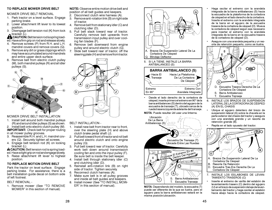
TO REPLACE MOWER DRIVE BELT

MOWER DRIVE BELT REMOVAL

1.Park tractor on a level surface. Engage parking brake.

2.Lower attachment lift lever to its lowest position.

3.Disengage belt tension rod (K) from lock

bracket (L).

CAUTION:Belttensionrodisspringload- ed. Have a firm grip on rod and release slowly.

4.Remove screws (P) from R.H. and L.H. mandrel covers and remove covers (Q).

5.Remove any dirt or grass clippings which may have accumulated around mandrels and entire upper deck surface.

6.Remove belt from electric clutch pulley (M), both mandrel pulleys (R) and all idler pulleys (S).

P

Q

LM

P

K

Q

R

S

R

MOWER DRIVE BELT INSTALLATION

1.Install belt around both mandrel pulleys

(R) and around idler pulleys (S) as shown.

2.Install belt onto electric clutch pulley (M). IMPORTANT: Check belt for proper routing in all mower pulley grooves.

3.Reassemble R.H. and L.H. mandrel cov- ers (Q). Securely tighten all screws.

4.Engage belt tension rod (K) on locking

bracket (L).

CAUTION: Belt tension rod is spring load- ed.Haveatightgriponrodandengageslowly.

5.Raise attachment lift lever to highest position.

TO REPLACE MOTION DRIVE BELT

Park the tractor on level surface. Engage parking brake. For assistance, there is a belt installation guide decal on bottom side of left footrest.

BELT REMOVAL -

1.Remove mower (See “TO REMOVE MOWER” in this section of manual).

NOTE: Observe entire motion drive belt and position of all belt guides and keepers.

2.Disconnect clutch wire harness (A).

3.Remove anti-rotation link (B) on right side of tractor.

4.Remove belt from stationary idler (C) and clutching idler (D).

5.Pull belt slack toward rear of tractor. Carefully remove belt upwards from transmission input pulley and over cool- ing fan blades (F).

6.Remove belt downward from engine pulley and around electric clutch (G).

7.Slide belt toward rear of tractor, off the steering plate (H) and remove from tractor.

G


H

B


A

C


D


J


F


BELT INSTALLATION -

1.Install new belt from tractor rear to front, over the steering plate (H) and above clutch brake pedal shaft (J).

2.Pull belt toward front of tractor and roll belt around electric clutch and onto engine pulley (G).

3.Pull belt toward rear of tractor. Carefully work belt down around transmission cooling fan and onto the input pulley (F). Be sure belt is inside the belt keeper.

4.Install belt through stationary idler (C) and clutching idler (D).

5.Reinstall anti-rotation link (B) on right side of tractor. Tighten securely.

6.Reconnect clutch harness (A).

7.Make sure belt is in all pulley grooves and inside all belt guides and keepers.

8.Install mower (See “TO INSTALL MOW- ER” in this section of manual).

Q

A

02965

A. Brazos De Suspensión Lateral De La

Cortadora De Césped

Q. Blindaje Deflector

5.SI LA TIENE, INSTALE LA BARRA ANTIBALANCEO (S)

BARRA ANTIBALANCEO (S)

Hacia El

Hacia La Plataforma

Transeje

De La Cortadora


De Césped

Extremo

Extremo Con

En 90°

Arandela Integrada

Desde el lado derecho de la cortadora de césped, inserte primero el extremo en 90° de la barra antibalanceo (S) dentro del agujero de la escuadra de transeje (T), ubicado cerca de la rueda trasera izquierda adelante del transeje.

NOTA: Puede resultar útil usar una linterna.

Ubicación

De La Barra

Antibalanceo (S)

Escuadra De Transeje (T)

Ubicada Entre Las Ruedas


En

90°


El

Extremo


Del

Agujero


ColoqueDentro


S


T

S.

Barra Antibalanceo

T.

Escuadra Transeje


NOTA: Dependiendo del modelo, la escuadra (T) puede ser diferente de la que se ilustra, pero el agujero para la barra antibalanceo estará en la misma posición/ubicación.

Haga oscilar el extremo con la arandela integrada de la barra antibalanceo (S) hacia la escuadra de la plataforma de la cortadora de césped en el lado derecho de la cortadora. Inserte el extremo con la arandela integrada de la barra en el agujero de la escuadra trasera de la cortadora de césped (D). Mueva la cortadora de césped según sea necesario para insertar el extremo con la arandela integrada de la barra en la escuadra trasera de la cortadora de césped (D).

Asegure con una arandela pequeña y un res- orte de retención pequeño, como se ilustra.


T

S


D


D. Escuadra Trasera Derecha De La


Cortadora De Césped

S.

Barra Antibalanceo

T.

Escuadra Transeje

6.INSTALE LOS BRAZOS DE SUSPENSIÓN LATERAL DE LA CORTADORA DE CÉSPED

(A) EN EL CHASIS

Ubique el agujero delantero del brazo de suspensión lateral (A) sobre la chaveta en la parte exterior del chasis del tractor y asegure con una arandela grande y un resorte de retención grande (B).

Repita en el lado opuesto del tractor.

A

B

D


A. Brazos De Suspensión Lateral De La


Cortadora De Césped


B. Resorte De Retención


D. Escuadra Tras-Era Derecha De La


Cortadora De Césped


7.INSTALE LOS ESLABONES DE LEVAN- TAMIENTO TRASEROS (C)

Inserte el extremo de varilla del eslabón de levantamiento trasero (C) dentro del agujero

(U) en el brazo de suspensión del eje de levan- tamiento del tractor y haga oscilar el eslabón hacia abajo hacia la cortadora de césped.

28

45

Page 28
Image 28
Sears 917.28861 owner manual Barra Antibalanceo S, To Replace Mower Drive Belt, To Replace Motion Drive Belt

917.28861 specifications

The Sears 917.28861 is a well-respected lawn tractor that has garnered attention for its robust features and reliable performance. This model is often recognized for its practicality, making it suitable for a wide range of lawn care tasks.

One of the standout features of the Sears 917.28861 is its powerful engine. Equipped with a reliable gas-powered engine, this lawn tractor provides ample horsepower to tackle various terrains and grass types. The engine is designed for efficiency, ensuring that users can maintain their lawns without excessive fuel consumption.

The cutting deck is another prominent characteristic of the 917.28861. Typically featuring a wide cutting width, this design allows users to cover larger areas in less time. The adjustable cutting heights provide flexibility to cater to different grass lengths and types. This feature ensures that lawns can be maintained according to individual preferences while promoting healthy grass growth.

The ergonomics of the 917.28861 are noteworthy as well. With an adjustable seat and user-friendly dashboard controls, operators can navigate and operate the tractor comfortably. The steering design allows for ease of maneuverability, especially in tight spaces like gardens or around flower beds.

A significant aspect of this model is its durability. Built with high-quality materials, the Sears 917.28861 is designed to withstand the rigors of regular use. This level of construction not only extends the lifespan of the tractor but also reduces the need for frequent repairs or part replacements, making it a cost-effective choice for homeowners.

Another key feature is the transmission system. The 917.28861 often includes a hydrostatic transmission, allowing for smooth and responsive speed adjustments. This technology provides a seamless driving experience, enabling users to control their pace without the hassle of shifting gears manually.

Additionally, the model may come with various attachments, enhancing versatility. Users can easily attach tools for tasks such as mulching, bagging, or even snow removal, making the Sears 917.28861 a multifunctional machine that can adapt to seasonal needs.

In summary, the Sears 917.28861 stands out for its powerful engine, durable construction, adjustable cutting capabilities, and user-friendly design. Whether tackling a small yard or a larger property, this lawn tractor is designed to simplify lawn care tasks while delivering consistent and reliable performance. Its combination of features and technologies makes it a valuable addition to any homeowner’s landscaping equipment lineup.