Manuals
/
Security 100
/
Household Appliance
/
Garage Door Opener
Security 100
KE-265
manual
Preparing for Installation, Keypad Options, System Components
Models:
KE-265
1
4
14
14
Download
14 pages
12.83 Kb
1
2
3
4
5
6
7
8
Troubleshooting
Specs
Install
Tamper Alarm Lockout
Connecting the Locking Device
Warranty
System Hardware Setup
Default Î 5 seconds
Page 4
Image 4
Page 3
Page 5
Page 4
Image 4
Page 3
Page 5
Contents
Installation and Operations Manual
Keyless Entry Access Control System
KE-265
Table of Contents
ESSEX ELECTRONICS, INC
KE-265 Series
Document Information
System Specifications
Introduction
Overview
Input Requirements
Keypad Options
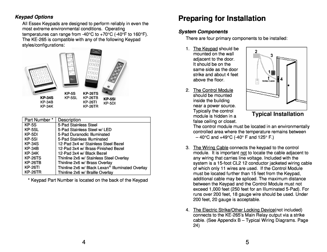
Preparing for Installation
System Components
Prepare the Keypad for Installation
The Installation Procedure
Required Tools
Install the Wiring Cable
Installing the Control Module
Connecting the Locking Device
Battery Backup
System Hardware Setup
Setting Relay Options
Remote By-Pass
Anti-Tailgating
Tamper Alarm Lockout
System Programming
Overview of System Code Programming
Overview of the Master Code
Programming the Master Code
Programming Door Open Time
Programming User Codes
Default Î 5 seconds
Troubleshooting
I Changed or Deleted a code, but the old code still unlocks the door
The Door opens with the first press on the Keypad
Keypad is completely dead
5 YEAR LIMITED WARRANTY
Repairs and Warranty
Repair Policy
Appendix A - Circuit Board Layout
DISCLAIMER OF WARRANTIES LIMITATION OF BUYER’S REMEDIES
Appendix B- Typical Wiring Diagrams
Top
Page
Image
Contents