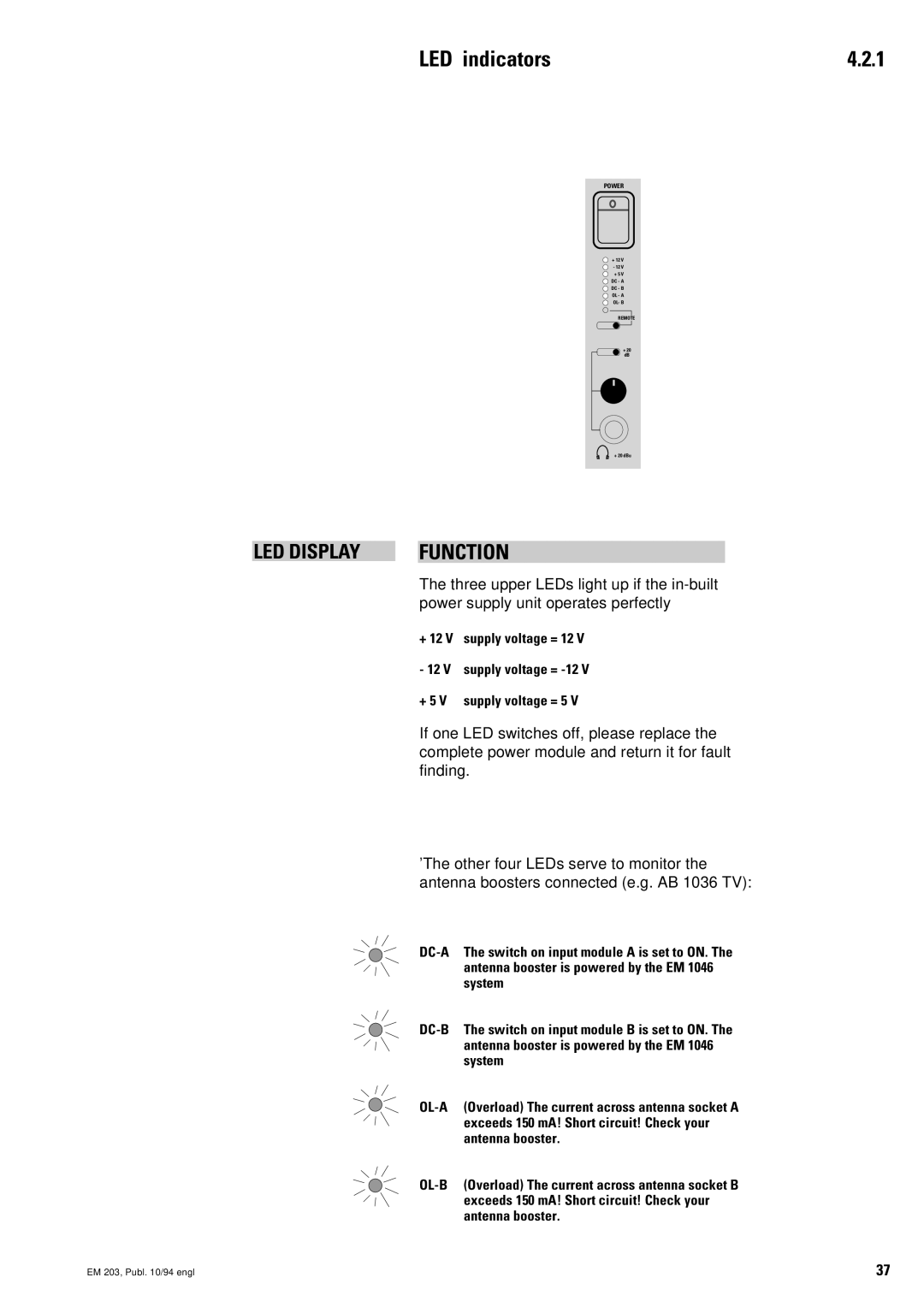
LED indicators | 4.2.1 |
POWER |
+ 12 V |
- 12 V |
+ 5 V |
DC - A |
DC - B |
OL - A |
OL- B |
REMOTE |
+ 20 |
dB |
+ 20 dBu |
LED DISPLAY |
| FUNCTION |
The three upper LEDs light up if the
+12 V supply voltage = 12 V - 12 V supply voltage =
+5 V supply voltage = 5 V
If one LED switches off, please replace the complete power module and return it for fault finding.
'The other four LEDs serve to monitor the antenna boosters connected (e.g. AB 1036 TV):
EM 203, Publ. 10/94 engl | 37 |