Mains connection | 3.1 |
Power is supplied by a
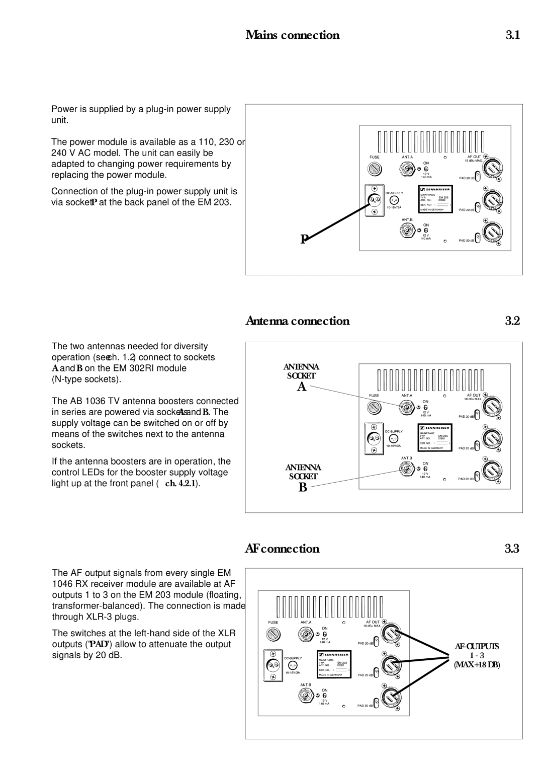
The power module is available as a 110, 230 or 240 V AC model. The unit can easily be adapted to changing power requirements by replacing the power module.
Connection of the
The two antennas needed for diversity operation (see ch. 1.2) connect to sockets A and B on the EM 302RI module
The AB 1036 TV antenna boosters connected in series are powered via sockets A and B. The supply voltage can be switched on or off by means of the switches next to the antenna sockets.
If the antenna boosters are in operation, the control LEDs for the booster supply voltage light up at the front panel (→ ch. 4.2.1).
P
Antenna connection | 3.2 |
ANTENNA
SOCKET
A
ANTENNA
SOCKET
B
AF connection | 3.3 |
The AF output signals from every single EM 1046 RX receiver module are available at AF outputs 1 to 3 on the EM 203 module (floating,
The switches at the
1 - 3
(MAX +18 DB)