MAINTENANCE |
| PRESSURE | ||
Removal of Soot from Heating Coil: | Burner Nozzle: |
| ||
In the heating process, fuel residue in the form of soot | Keep the tip free of surface deposits by wiping it with a | |||
deposits may develop between the heating coil pipe, | clean, solvent saturated cloth, being careful not to plug | |||
and block air flow which will affect burner combustion. | or enlarge the nozzle. For maximum efficiency, replace | |||
WASHER | ||||
When soot has been detected on visual observation, | the nozzle each season. |
| ||
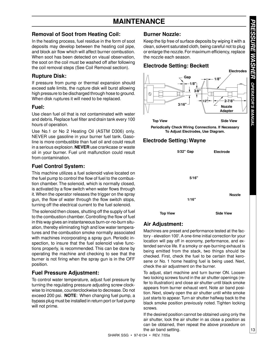
the soot on the coil must be washed off after following | Electrode Setting: Beckett |
| ||
the coil removal steps (See Coil Removal section). |
| |||
| Electrodes | |||
Rupture Disk: |
| |||
Gap | 1/8" | |||
If pressure from pump or thermal expansion should |
|
| ||
1/8" |
| OPERATOR’S | ||
exceed safe limits, the rupture disk will burst allowing | 3/8" |
| ||
high pressure to be discharged through hose to ground. |
| |||
|
| |||
When disk ruptures it will need to be replaced. | 1/2" | |||
| ||||
Fuel: | 3/16" | Nozzle | ||
| ||||
Use clean fuel oil that is not contaminated with water |
| Adapter | MANUAL | |
|
| |||
and debris. Replace fuel filter and drain tank every 100 | Top View | Side View | ||
hours of operation. | ||||
Periodically Check Wiring Connections. If Necessary | ||||
Use No.1 or No 2 Heating Oil (ASTM D306) only. |
| |||
To Adjust Electrodes, Use Diagram. |
| |||
NEVER use gasoline in your burner fuel tank. Gaso- | Electrode Setting: Wayne |
|
| |
line is more combustible than fuel oil and could result |
|
| ||
in a serious explosion. NEVER use crankcase or waste | 5/32" Gap | Electrode |
| |
oil in your burner. Fuel unit malfunction could result |
| |||
from contamination. |
|
|
| |
Fuel Control System: |
|
|
| |
This machine utilizes a fuel solenoid valve located on |
|
|
| |
the fuel pump to control the flow of fuel to the combus- |
| 5/16" |
| |
tion chamber. The solenoid, which is normally closed, |
|
|
| |
is activated by a flow switch when water flows through |
|
|
| |
it. When the operator releases the trigger on the spray |
| Nozzle |
| |
|
| |||
gun, the flow of water through the flow switch stops, |
| 1/16" |
| |
turning off the electrical current to the fuel solenoid. |
|
|
| |
The solenoid then closes, shutting off the supply of fuel | Top View | Side View | ||
to the combustion chamber. Controlling the flow of fuel | ||||
|
|
| ||
in this way gives an instantaneous | Air Adjustment: |
|
| |
ation, thereby eliminating high and low water tempera- |
|
| ||
Machines are preset and performance tested at the fac- | ||||
tures and the combustion smoke normally associated | ||||
tory - elevation 100'. A | ||||
with machines incorporating a spray gun. Periodic in- | ||||
location will pay off in economy, performance, and ex- | ||||
spection, to insure that the fuel solenoid valve func- | ||||
tended service life. If a smoky or | ||||
tions properly, is recommended. This can be done by | ||||
being emitted from the stack, two things should be | ||||
operating the machine and checking to see that the | ||||
checked. First, check the fuel to be certain that kero- | ||||
burner is not firing when the spray gun is in the OFF | ||||
sene or No. 1 home heating fuel is being used. Next, | ||||
position. | ||||
check the air adjustment on the burner. | ||||
| ||||
Fuel Pressure Adjustment: | To adjust, start machine and turn burner ON. Loosen | |||
To control water temperature, adjust fuel pressure by | two locking screws found in the air shutter openings (re- | |||
fer to illustration) and close air shutter until black smoke | ||||
turning the regulating pressure adjusting screw clock- | ||||
appears from burner exhaust vent. Note air band posi- | ||||
wise to increase, counterclockwise to decrease. Do not | ||||
tion. Next, slowly open the air shutter until white smoke | ||||
exceed 200 psi. NOTE: When changing fuel pump, a | ||||
just starts to appear. Turn air shutter halfway back to the | ||||
bypass plug must be installed in return port or fuel pump | ||||
black smoke position previously noted. Tighten locking | ||||
will not prime. | ||||
screws. |
|
| ||
|
|
| ||
| If the desired position cannot be obtained using only the | |||
| air shutter, lock the air shutter in as close a position as | |||
| can be obtained, then repeat the above procedure on | |||
| the air band setting. | 13 | ||
SHARK SSG •