Connecting Pin Assignments
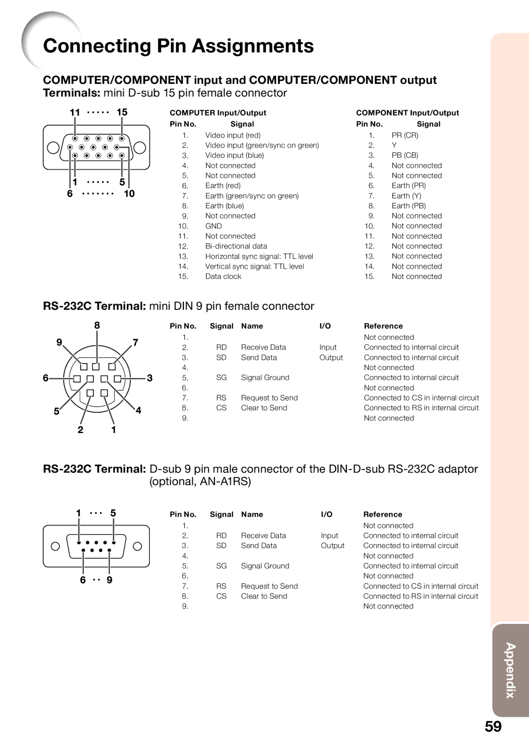
COMPUTER/COMPONENT input and COMPUTER/COMPONENT output
Terminals: mini D-sub 15 pin female connector
11 |
| 15 |
|
| COMPUTER Input/Output |
| COMPONENT Input/Output | ||||||||
|
|
|
|
|
|
|
|
|
| Pin No. | Signal |
| Pin No. | Signal | |
|
|
|
|
|
|
|
|
|
| 1. | Video input (red) |
| 1. | PR (CR) | |
|
|
|
|
|
|
|
|
|
|
| |||||
|
|
|
|
|
|
|
|
|
| 2. | Video input (green/sync on green) |
| 2. | Y | |
|
|
|
|
|
|
|
|
|
| 3. | Video input (blue) |
| 3. | PB (CB) | |
|
|
|
|
|
|
|
|
|
| 4. | Not connected |
| 4. | Not connected | |
|
|
|
|
|
|
|
|
|
| 5. | Not connected |
| 5. | Not connected | |
|
| 1 |
| 5 |
|
|
| ||||||||
|
|
|
|
| 6. | Earth (red) |
|
| 6. | Earth (PR) | |||||
6 |
|
| 10 |
|
|
| |||||||||
|
|
| 7. | Earth (green/sync on green) |
| 7. | Earth (Y) | ||||||||
|
|
|
|
|
|
|
|
|
| 8. | Earth (blue) |
| 8. | Earth (PB) | |
|
|
|
|
|
|
|
|
|
| 9. | Not connected |
| 9. | Not connected | |
|
|
|
|
|
|
|
|
|
| 10. | GND |
|
| 10. | Not connected |
|
|
|
|
|
|
|
|
|
| 11. | Not connected |
| 11. | Not connected | |
|
|
|
|
|
|
|
|
|
| 12. |
| 12. | Not connected | ||
|
|
|
|
|
|
|
|
|
| 13. | Horizontal sync signal: TTL level |
| 13. | Not connected | |
|
|
|
|
|
|
|
|
|
| 14. | Vertical sync signal: TTL level |
| 14. | Not connected | |
|
|
|
|
|
|
|
|
|
| 15. | Data clock |
|
| 15. | Not connected |
|
|
|
| ||||||||||||
8 |
|
|
|
|
| Pin No. | Signal | Name | I/O | Reference | |||||
9 |
|
|
| 7 |
| 1. |
|
|
| Not connected | |||||
|
|
|
| 2. | RD | Receive Data | Input | Connected to internal circuit | |||||||
|
|
|
|
|
|
|
|
|
| ||||||
|
|
|
|
|
|
|
|
|
| 3. | SD | Send Data | Output | Connected to internal circuit | |
6 |
|
|
|
|
|
|
|
| 3 | 4. |
|
|
| Not connected | |
|
|
|
|
|
| 5. | SG | Signal Ground |
| Connected to internal circuit | |||||
|
|
|
|
|
| ||||||||||
|
|
|
|
|
|
|
|
|
| 6. |
|
|
| Not connected | |
|
|
|
|
|
|
|
|
|
| 7. | RS | Request to Send |
| Connected to CS in internal circuit | |
5 |
|
|
| 4 |
| 8. | CS | Clear to Send |
| Connected to RS in internal circuit | |||||
|
|
|
| 9. |
|
|
| Not connected | |||||||
|
|
|
|
|
|
|
|
|
|
|
|
| |||
2 |
| 1 |
|
|
|
|
|
|
|
|
|
| |||
1 |
| 5 | Pin No. | Signal | Name | I/O | Reference | |||
|
|
|
|
|
| 1. |
|
|
| Not connected |
|
|
|
|
|
| 2. | RD | Receive Data | Input | Connected to internal circuit |
|
|
|
|
|
| 3. | SD | Send Data | Output | Connected to internal circuit |
|
|
|
|
|
| 4. |
|
|
| Not connected |
|
|
|
|
|
|
|
|
| ||
|
|
|
|
|
| 5. | SG | Signal Ground |
| Connected to internal circuit |
6 | 9 |
| 6. |
|
|
| Not connected | |||
| 7. | RS | Request to Send |
| Connected to CS in internal circuit | |||||
|
|
|
|
|
|
| ||||
|
|
|
|
|
| 8. | CS | Clear to Send |
| Connected to RS in internal circuit |
|
|
|
|
|
| 9. |
|
|
| Not connected |
Appendix
59